FANUC Robot Connectivity Guide
Overview
FANUC robots do not use FOCAS. FOCAS is for FANUC CNC controls only. Robots are connected to MachineMetrics using one of the methods below, listed from easiest to hardest.
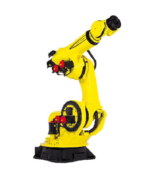
The connection method depends on the controller behind the robot — R-30iB, R-30iB Plus or R-50iA — not on the arm itself.
| Method | Controller | FANUC options needed | Robot programming needed | Difficulty |
|---|---|---|---|---|
| OPC-UA | R-30iB Plus, R-50iA | OPC UA Server | Small (part counter) | Easiest |
| Modbus/TCP | R-30iB, R-30iB Plus | Modbus TCP | Small (part counter, register mapping) | Easy |
| Digital I/O | Any | None | Small (cycle complete output) | Moderate (wiring) |
| MQTT | R-30iB Plus, R-50iA | MQTT and KAREL | Large (custom KAREL program) | Hardest |
MachineMetrics only needs three things from a robot: execution state (running, paused, faulted), part count, and part or program name. Anything beyond that is optional.
For every method in this guide, the robot program must count cycles. MachineMetrics reads the count; it does not create it. See Robot Program Changes.
Who does what
| Task | Owner |
|---|---|
| Purchase FANUC software options | Customer (via FANUC or integrator) |
| Set the robot IP address | Customer or integrator |
| Robot program changes (part counter, status registers, KAREL) | Customer or integrator |
| Wiring for Digital I/O | Customer, integrator, or MachineMetrics onsite services |
| Add the machine and adapter script in MachineMetrics | MachineMetrics |
| Validate data | MachineMetrics |
MachineMetrics does not modify robot programs or controller configuration.
Before You Begin
Step 1: Identify the controller
The controller model decides which methods are available. Check the label on the controller cabinet or the teach pendant startup screen.
- R-30iB Plus (software V9.x): all methods available
- R-30iB (software V8.x): Modbus/TCP and Digital I/O. OPC-UA and MQTT are not available.
- R-50iA: all methods available
Step 2: Check the software version and installed options
- On the teach pendant, press MENU
- Select STATUS, then Version ID
- Note the Software Edition No. (for example V9.30P/xx)
- On the same screen, view the Order File (installed options list)
- Take a photo or screenshot of the options list and send it to your MachineMetrics contact
Look for any of the following in the options list:
| Option | Used for |
|---|---|
| OPC UA Server (J997) | Method 1 |
| Advanced EtherNet/IP Scanner Package (R887) | Includes OPC UA Server access |
| Modbus TCP | Method 2 |
| KAREL (R632) | Required for MQTT |
| MQTT | Method 4 |
If the option you need is not installed, contact FANUC or your robot integrator for a quote.
Network Setup (All Ethernet Methods)
Step 1: Choose the Ethernet port
The R-30iB and R-30iB Plus have two Ethernet ports on the main board (Port 1 and Port 2). One may already be in use for a PLC or cell network.
- Use a port that is not already connected to the cell's safety or PLC network, or confirm with the integrator that MachineMetrics traffic can share it
- Do not change the IP address of a port the cell PLC depends on
Step 2: Set the IP address on the teach pendant
- Press MENU
- Select SETUP, then press F1 [TYPE] and select Host Comm
- Select TCP/IP and press DETAIL
- Select the port you are configuring (Port 1 or Port 2)
- Set the following, using values from your IT team:
- Robot IP addr
- Subnet Mask
- Router IP addr (gateway, only if the Edge is on a different subnet)
- Cycle power on the controller for the change to take effect
Step 3: Test the connection
From a laptop or the MachineMetrics Edge on the same network, ping the robot IP. If ping fails, check the cable, port, subnet, and any firewalls before continuing.
Robot Program Changes
These changes are made by the customer or integrator. They are needed for every Ethernet method.
Part counter
Add a line at the end of the robot's main production program (after the part is complete) to increment a numeric register:
R[1]=R[1]+1 ;
Use any unused register. The examples in this guide use R[1]. Tell MachineMetrics which register you used.
Execution state
MachineMetrics needs to know whether the robot is running, paused, or faulted. The recommended approach is to have Background Logic copy the robot's UOP status outputs into a numeric register, so the same register works for OPC-UA and Modbus/TCP.
Recommended register map:
| Register | Contents |
|---|---|
| R[1] | Part count (increments once per completed part) |
| R[2] | Program running (1 = running, 0 = not running), from UO[3] PROGRUN |
| R[3] | Paused (1 = paused), from UO[4] PAUSED |
| R[4] | Fault (1 = faulted), from UO[6] FAULT |
Program name (optional)
If program name is wanted, the integrator can write the active program or part name into a string register (for example SR[1]) at program start.
Method 1: OPC-UA
Best for: R-30iB Plus and R-50iA controllers. This is the easiest method.
FANUC's built-in OPC UA server exposes the robot's I/O and registers. It supports up to 10 OPC-UA clients at a time.
On the robot controller
- Confirm the OPC UA Server option (J997) is installed (see Before You Begin). It may also be included in the Advanced EtherNet/IP Scanner Package (R887).
- Complete Network Setup and Robot Program Changes.
- Enable the OPC UA server on the controller.
The OPC-UA endpoint is fixed:
opc.tcp://<robot-ip>:4880/FANUC/NanoUaServer
FANUC robots use port 4880, not the standard OPC-UA port 4840. If port 4880 does not respond, the OPC UA Server option is not enabled.
Test with an OPC-UA client
Before adding the robot in MachineMetrics, connect with UaExpert (free from the OPC Foundation):
- Add a server using the endpoint above
- Connect with Security Mode None (unless security has been configured on the robot)
- Browse the address space and find the HoldingRegisters node
- Watch R[1] while the robot runs a cycle to confirm the part counter increments
In MachineMetrics
- Go to Assets > Machines and click Add Machine
- Enter the machine name, make (FANUC), and model, then select the Edge device
- Set Adapter Type to OPC-UA
- Set the connection string to
opc.tcp://<robot-ip>:4880/FANUC/NanoUaServer - Paste the adapter script below into the adapter configuration
- Click Test Connection, then Save
- Map the data items on the Data Mapping tab
Sample adapter script
This script assumes the recommended register map and that the holding registers node is ns=1;i=304. Confirm the node ID by browsing the robot before use.
version: 2
security-mode: None
force-read-on-connect: true

tags:
  part-counter:
    path: ns=1;i=304
    index: 0      # R[1]
  prog-running:
    path: ns=1;i=304
    index: 1      # R[2]
  paused:
    path: ns=1;i=304
    index: 2      # R[3]
  fault:
    path: ns=1;i=304
    index: 3      # R[4]

variables:
  execution:
    - state:
      - INTERRUPTED: fault == 1
      - FEED_HOLD: paused == 1
      - ACTIVE: prog-running == 1
      - READY: true

  part-count:
    - source: part-counter
    - value-increase
    - count

data-items:
  - execution
  - part-count
  - part-counter
Reading array elements with index requires OPC-UA adapter version 1.34.2 or later.
Method 2: Modbus/TCP
Best for: R-30iB (non-Plus) controllers, or any R-30iB Plus without the OPC UA Server option.
The robot acts as a Modbus/TCP server on port 502. MachineMetrics reads the robot's numeric registers.
On the robot controller
- Confirm the Modbus TCP option is installed (see Before You Begin)
- Complete Network Setup and Robot Program Changes
- Enable the Modbus TCP server on the controller
- Obtain the Modbus register map from the FANUC Modbus TCP manual or the integrator, showing which Modbus address holds R[1] to R[4]
Test with a Modbus client
Use a Modbus client tool (for example Modbus Poll) to read holding registers from <robot-ip>:502. Confirm the part counter register increments when the robot completes a cycle.
In MachineMetrics
- Go to Assets > Machines and click Add Machine
- Enter the machine details and select the Edge device
- Set Adapter Type to Modbus TCP
- Set the Connection Address to the IP and port together, for example
10.20.112.52:502. Entering the IP alone will leave the machine offline. - Paste the adapter script below into the Configure your adapter field
- Click Test Connection, then Save
- Map the data items on the Data Mapping tab
Sample adapter script
Replace the addresses with the ones from the robot's Modbus register map.
version: 2
unit-id: 1
address-space: mixed

registers:
  part-counter:
    address: 40001    # R[1], replace with address from register map
    type: int16
    func: 3
  prog-running:
    address: 40002    # R[2]
    type: int16
    func: 3
  paused:
    address: 40003    # R[3]
    type: int16
    func: 3
  fault:
    address: 40004    # R[4]
    type: int16
    func: 3

variables:
  execution:
    - state:
      - INTERRUPTED: fault == 1
      - FEED_HOLD: paused == 1
      - ACTIVE: prog-running == 1
      - READY: true

  part-count:
    - source: part-counter
    - value-increase
    - count

data-items:
  - execution
  - part-count
  - part-counter
Method 3: Digital I/O
Best for: any robot where no software option can be purchased, or where Ethernet access to the controller is not allowed.
The robot's digital outputs are wired into a Sealevel I/O module, which MachineMetrics reads. This method needs no FANUC software options, but gives execution state and part count only (no program name).
On the robot controller
The integrator assigns digital outputs for:
- Running (for example mirrored from UO[3] PROGRUN)
- Fault (for example mirrored from UO[6] FAULT)
- Cycle complete (a short pulse at the end of each part, added to the robot program)
Wiring and MachineMetrics setup
Follow the Digital I/O Connectivity Guide for hardware, wiring, and adapter setup.
Method 4: MQTT (Advanced)
Best for: R-30iB Plus and R-50iA robots where the customer or integrator wants to send more data than registers allow (alarms, cycle times, custom values) and has KAREL programming expertise.
MQTT is not a setting that can be switched on. The robot only publishes what a custom KAREL program tells it to publish. This requires two FANUC options and a KAREL programmer. MachineMetrics does not write or support KAREL programs.
How it works
FANUC Robot (KAREL program, MQTT client)
     → publishes to →
MQTT Broker (on the MachineMetrics Edge, or customer-hosted)
     → subscribed by →
MachineMetrics Edge Adapter
The robot is an MQTT client only and cannot act as a broker, so a broker is always required. MachineMetrics can host a Mosquitto broker on the Edge device.
On the robot controller
- Confirm both the MQTT and KAREL (R632) options are installed
- Complete Network Setup
- The integrator writes a KAREL program that:
- Connects to the broker at
<edge-ip>:1883(or the customer broker) - Uses a unique MQTT Client ID for each robot
- Publishes a JSON message on a defined topic whenever status changes and at the end of each cycle
- Connects to the broker at
- The program is compiled (ktrans, included with ROBOGUIDE), loaded onto the controller, and set to run in the background
Recommended topic and message format:
Topic: fanuc/<robot-name>/status
{
  "running": 1,
  "paused": 0,
  "fault": 0,
  "program": "MAIN_PART_A",
  "partcount": 1532
}
In MachineMetrics
- Go to Assets > Machines and click Add Machine
- Set the Data Collection Method to MQTT
- Set the connection address:
- Edge-hosted broker:
mqtt://customservices_mosquitto_1 - Customer broker:
mqtt://<broker-ip>:1883
- Edge-hosted broker:
- Paste the adapter script below, then Save
- Map the data items on the Data Mapping tab
Sample adapter script
version: 2

topics:
  fanuc/robot01/status:
    json:
      prog-running: running
      paused: paused
      fault: fault
      program: program
      part-counter: partcount

variables:
  execution:
    - state:
      - INTERRUPTED: fault == 1
      - FEED_HOLD: paused == 1
      - ACTIVE: prog-running == 1
      - READY: true

  part-count:
    - source: part-counter
    - value-increase
    - count

data-items:
  - execution
  - part-count
  - program
Test the broker
From a computer on the same network:
mosquitto_sub -h <broker-ip> -t "fanuc/#" -v
Messages should appear when the robot changes state or completes a cycle.
Not Supported
| Method | Why |
|---|---|
| FOCAS | FANUC CNC controls only, not robots |
| EtherNet/IP | The MachineMetrics EtherNet/IP adapter reads Allen Bradley Logix PLC tags. FANUC robots run as EtherNet/IP adapter devices and do not expose tags. |
| HMI Device (SNPX) | No MachineMetrics adapter |
Troubleshooting
| Symptom | Check |
|---|---|
| Cannot ping robot | Correct port used, IP and subnet set, controller power cycled after IP change |
| OPC-UA will not connect | OPC UA Server option installed and enabled, port 4880 (not 4840), full endpoint path included |
| Modbus will not connect | Modbus TCP option installed and server enabled, connection address includes :502 |
| Connected but part count stays at zero | Confirm the robot program increments the register, and that the register increments in UaExpert or a Modbus client |
| Execution always READY | Status registers not being updated by Background Logic, or wrong register addresses in the script |
| MQTT connected but no data | KAREL program running, topic names match the script exactly, unique Client ID per robot |
For general validation, see the Connectivity Validation Guide.
Getting Help
Contact MachineMetrics Support with:
- Controller model and software version
- Photo of the installed options list
- Robot IP address and the method you are using
- Register numbers used for part count and status