Digital I/O Connectivity
You wire the machine's own electrical signals — stack lights, relay contacts, M-code outputs, or motor current through a transducer — into an I/O module that MachineMetrics polls over Modbus TCP.
Adding a Digital I/O machine in MachineMetrics configures the path to your hardware over Modbus/TCP. It does not map inputs, coils and registers to utilization, part count or anything else. You must add an adapter script that interprets your wired signals. Without it the hardware is reachable but no production data appears — the most common reason an I/O install is believed to have failed. See Adapter Scripts.
What is I/O Connectivity?
Digital I/O connects equipment through electrical signals and sensors rather than a digital protocol. It is the universal fallback beneath every other connectivity method: if activity can be sensed, it can be monitored.
I/O is a fallback, not a preferred path. Where a native protocol is available, that connection is strongly preferred, because it surfaces data that cannot be inferred from an electrical signal, including program and part identification, cycle detail, and alarms. Choose I/O when no native protocol exists, or when a customer decides not to license one. In that second case, connecting by I/O means accepting activity-level data in place of the richer native data set. That is a tradeoff, not an equivalent option.
What can be collected through I/O is determined by which signals are accessible and which sensors can be fitted to them, not by the equipment's age, category, or whether it is a machine tool at all. A current transducer on motor power is the common approach for machine tools, but utilization can be derived from any signal that indicates activity, such as a proximity sensor detecting movement or output.
How It Works:
MachineMetrics uses a piece of hardware (typically a Sealevel or WISE device) installed in the machine's electrical cabinet. This hardware module connects to electrical signals from the machine to monitor activity and production.
Our Standard Approach:
- Utilization Signal (Machine Activity):
- Install a current transducer (CT) on a cable drawing current
- Typically attached to the spindle motor cable
- Detects when the machine is running vs. idle by monitoring motor current
- Part Count Signal:
- Capture a signal that indicates when a part is complete
- Lathes: Often use bar feed signal
- Mills: Often use fixture clamp signal or pallet changer
- Other machines: Part eject, part counter relay, etc.
The hardware module reads these electrical signals and sends the data to MachineMetrics over your network using Modbus TCP protocol.
When to Use I/O
Use I/O connectivity when:
- The machine does not support a modern protocol (FOCAS, MTConnect, OPC-UA)
- Older legacy equipment (pre-2000 machines)
- Simple machine tools without networked controls
- Non-CNC machines (press brakes, injection molding, grinders, assembly equipment)
- Equipment with accessible electrical signals but no data interface
- A native protocol exists but requires a vendor license the customer chooses not to purchase, for example Zeiss CMMs, which require the MTConnect Data Interface license
- Any other equipment whose activity can be sensed
The entries above are examples, not the full set.
Key Technical Concepts
Understanding these terms will help as you configure I/O connectivity:
- Wet Contact: Signal provides its own voltage source (e.g., 24VDC output from PLC)
- Dry Contact: Simple switch closure, requires external voltage source
- Current Transducer (CT): Sensor that outputs proportional voltage or current based on AC motor current
- Optically Isolated: Electrical isolation between input and system ground (3000VDC+ typical)
- Modbus TCP: Industry-standard digital protocol for reading/writing data over Ethernet
Choosing Your Hardware
| Sealevel eI/O-170E | WISE-4050(/LAN) | WISE-4012 | |
|---|---|---|---|
| Discrete inputs | 2 (dry contact only) | 4 (dry or wet) | — |
| Analog inputs | 8 × 0–10V | — | 4 × universal |
| Hardware counter | No | Yes, to 3kHz | No (2Hz sampling) |
| Wireless | No | Yes on the WISE-4050 | No |
| Typical use | Spindle CT for utilization | Several discrete signals, fast part counting | CT where only a WISE is available |
| Setup | Sealevel | WISE | WISE |
Pick on inputs first. A current transducer for utilization needs an analog input, which means Sealevel (or a WISE-4012). Several discrete signals, or part counting faster than about 10Hz, means a WISE-4050. A machine needing both a CT and four discrete signals needs two modules.
Retired Hardware
LabJack T4
The LabJack T4 is a network-connected I/O module for analog and digital inputs. It sits on a small dedicated network between the Edge device and the module, and is added in MachineMetrics using the Digital IO (T4 Module) integration type.
- Connection Address: Enter the module's IP address only — do not include a port number
- Hardware sourcing: MachineMetrics no longer sources or ships T4 modules — customers who want to use a T4 will need to source the hardware themselves
- Both existing and new installations are fully supported
LabJack T7
The LabJack T7 is a network-connected I/O module for analog and digital inputs, added in MachineMetrics using the Digital IO (T7 Module) integration type. It has roughly twice the scan throughput of the T4.
- Thermocouple inputs: Thermocouple values cannot be streamed the way standard analog and digital signals are. When a T7 is used to read a thermocouple, it is integrated as a generic Modbus TCP device instead of the standard LabJack integration — this polls at a slower rate but provides access to the module's native thermocouple support
- Hardware sourcing: MachineMetrics no longer sources or ships T7 modules — customers who want to use a T7 will need to source the hardware themselves
- Both existing and new installations are fully supported
LabJack U3 (Legacy USB)
⚠️ RETIRED: No longer sold by MachineMetrics. Existing and new installations are fully supported; customers who want a U3 must source the hardware themselves.
The LabJack U3 is a USB-connected I/O data acquisition device used on legacy installations. It connects directly to the Edge device via USB cable and is wired the same as other I/O modules for analog and digital inputs.
How it connects:
- The U3 was used in IO WiFi installations, where the Edge device connected wirelessly to the network and the LabJack U3 connected to that Edge device via USB.
- This approach has been replaced by I/O devices that connect to the Edge over a network connection.
Connection Address display:
Because the connection is USB rather than networked, the U3 does not have its own IP address. On a machine using the LabJack U3 collection method, the Connection Address field in the Machines list will display USB with no IP — this is the expected display for this connection type.
Confirming the device is connected:
- Confirm the USB cable between the LabJack and the Edge device is securely connected and that the LabJack has power.
- The U3 cannot be pinged or reached remotely — it has no network address.
- If the physical connection looks correct and the machine still is not reporting, contact MachineMetrics Support. Support can confirm from the Edge device directly whether it recognizes the LabJack.
Module Power
The schematics on this page are reference wiring, drawn from the manufacturer datasheets. They are not a wiring diagram for your machine. Verify every connection against the machine's own electrical prints before you install, and confirm terminal labels and the Modbus map against the unit in front of you — they vary by firmware revision.

- Preferred source: the same 24VDC supply that drives the signals you monitor. One 0V reference avoids ground offsets and low-voltage alarms.
- Load is about 0.1A per module — Sealevel draws up to 3W, WISE 2.2W. Keep total supply load under 80% of its rating.
- Protect the tap. A 0.5–1A supplementary fuse or MCB, sized to the conductor (18–22 AWG).
- DC only. Sealevel accepts 9–30VDC, WISE 10–30VDC. Never 24VAC.
- PoE removes field power on the eI/O-170PoE only. WISE has no PoE input.
- Use one source per module. Never parallel two supplies.
This plate carries no signals, so it has no adapter script. Once the module is powered, confirm the PWR LED is lit and the module answers on its IP before wiring any signals.
Signal Selection Strategy
Utilization Signals
Goal: Determine if machine is ACTIVE or IDLE.
Preferred Methods (in order):
-
Current Transducer on Spindle (Most Reliable)
- Analog CT: Monitors actual motor current
- Set low threshold (1.0-1.5V) for low-speed detection
- Works on almost any spindle-driven equipment
-
Green Stack Light (If Accurate)
- Wet contact: 24VDC when machine running
- Simple and reliable
- Verify it accurately reflects in-cycle state
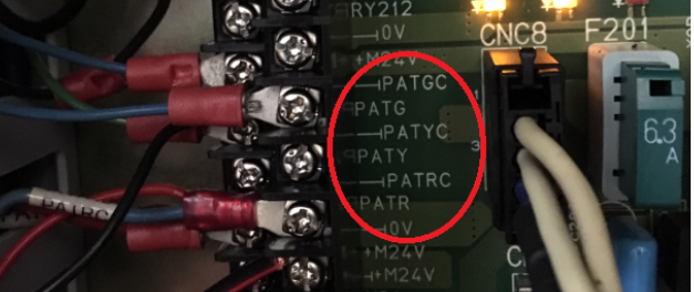
Stack light output terminals are typically labeled on the CNC terminal block inside the electrical cabinet. Look for PATGC / PATG (green — running), PATYC / PATY (yellow — idle/alarm), and PATRC / PATR (red — alarm).
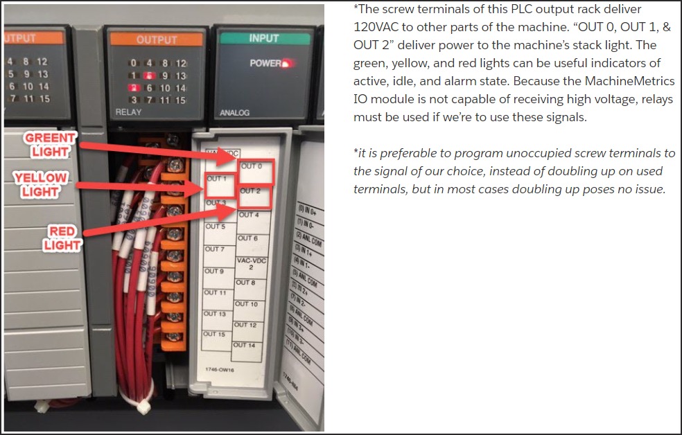
⚠️ Important: Many machines deliver 120VAC or 24VAC to stack light outputs — the MachineMetrics I/O module cannot receive high-voltage signals directly. If the PLC outputs high voltage, relays are required to step down or isolate the signal.
-
PLC Output "In Cycle" (If Available)
- Dedicated signal from PLC
- Most accurate when available
- May be labeled "Auto Mode", "Cycle Active", etc.
Part Count Signals
Goal: Detect when a part has been completed.
Preferred Methods (in order):
-
Part Count Relay (Ideal)
- Dedicated relay triggered by M-code in program
- Pulses briefly after each part
- Most reliable method
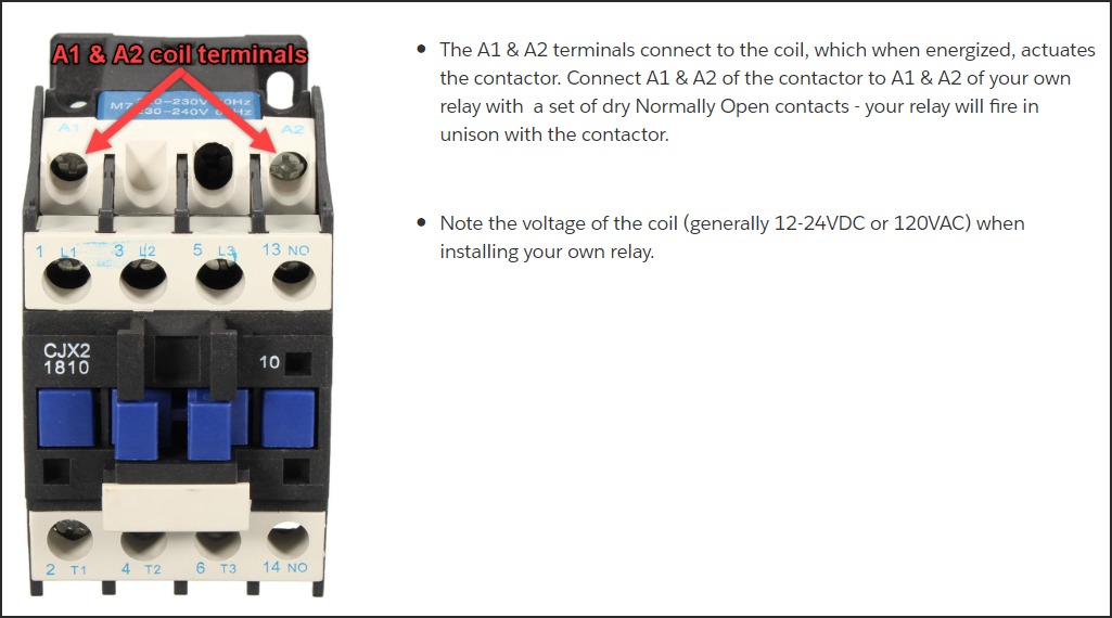
Many machining centers have spare M-code relays built in (e.g., M70/M71 on HMCs). You can also piggyback your own relay onto an existing contactor by wiring to the A1 & A2 coil terminals — your relay fires in unison with the machine's relay.
-
Pallet Changer Signal (Mills with Pallets)
- Signal when pallet changes
- Each pallet change = parts completed
- Monitor "Pallet Index Complete" or similar
-
Barfeeder Pulse (Lathes with Barfeeders)
- Signal when barfeeder advances
- Each advance = new part started
- May need logic: count on part eject, not bar advance
-
Part Ejector/Unloader
- Signal from part handling equipment
- Part catcher, conveyor, or robot
- May need combination logic (ejector AND auto mode)
-
Coolant Pump Pulse (Last Resort)
- ⚠️ Use only when other methods not available
- Requires two M-code pulses (on, off, on, off)
- Must use min-delta and max-delta for timing verification
- Can cause excessive coolant pump wear
- Requires program modifications
After wiring and configuring a part count signal, use the Connectivity Validation Guide to confirm the signal is behaving correctly — including how to spot bad counts on the Timeline before they affect production reporting.
Does the Signal Need a Relay?
The rule of thumb: if the signal has voltage on it and the input expects a contact — or the voltage is outside the input's range — add an interposing relay.
| Signal | Typical source | Sealevel eI/O-170E | WISE-4050(/LAN) |
|---|---|---|---|
| Dry contact | Spare M-code relay, limit switch | Direct — Opto n ↔ its C | Direct — DIx ↔ DI COM, SW2 ON |
| 24VDC sourcing (PNP) | PLC output, 24V stack light, Brother XTO (orange) | Relay — 24VDC coil | Direct — wet, SW2 OFF, DI COM → 0V |
| 24VDC sinking (NPN) | NPN PLC output, Brother XTO (gray) | Relay — coil from +24V to output | Direct — wet, SW2 OFF, DI COM → +24V |
| 5–9VDC logic | TTL / 5V sensor outputs | Relay | Relay — below the 10V logic-1 threshold |
| 24VAC / 120VAC / 240VAC | Stack lights, contactor coil circuits | Relay — AC coil, matched voltage | Relay — AC coil, matched voltage |
| Above 30VDC | 48V hydraulic / legacy controls | Relay | Relay |
| Analog CT, 0–10V | Spindle / axis motor current | Direct — Analog n ↔ Analog G | Not supported on WISE-4050. Direct on WISE-4012 via Vn± |
| CT with switch output | Current switch, adjustable trip | Direct — Opto n ↔ its C | Direct — dry, SW2 ON |
| High-speed pulse (>10Hz) | Encoder, prox on a fast line | Not recommended | Direct — counter mode, no mechanical relay |
| Wet and dry on one module | Mixed machine signals | Wet signals relayed | Relay the minority type — SW2 sets all four |
Interposing Relay Specification
- Coil: match the signal voltage and type — 24VDC, 24VAC or 120VAC.
- Contact: N.O. (SPDT acceptable). Gold-flashed or bifurcated, because it has to switch as little as 12mA reliably.
- Isolation: at least 2.5kV coil-to-contact, rated for the control voltage.
- Suppression: DC needs a flyback diode; AC needs an RC network or varistor.
- Form: a DIN-rail slim interface relay with an LED — Phoenix Contact PLC-RSC, Finder 38 series, IDEC RV8H.
- Timing: roughly 5–15ms to operate. Fine for part-count pulses of 100ms or longer. Use a solid-state relay, or WISE counter mode, for anything faster.
Wiring a relay changes nothing in the adapter script: the relay contact lands on a dry input, so the script reads it exactly as it would read any other dry contact.
In This Section
| Page | What it covers |
|---|---|
| Sealevel | Terminal reference, install, network setup, wiring patterns and current transducers |
| WISE | Terminal references for all three models, DIP switches, Wi-Fi and wired setup, wiring patterns and counter mode |
| Wiring Examples | Complete machines end to end, plus machine-specific integrations |
| Adapter Scripts | Adding the device in MachineMetrics, and worked scripts for every wiring pattern |
| Troubleshooting | Connection failures, undetected signals, CT tuning and false part counts |
Additional Resources
MachineMetrics Developer Documentation:
Sealevel Resources:
- SeaMAX Software Download: https://www.sealevel.com/software-seamax-windows
- eI/O-170 Product Page: https://www.sealevel.com
- Technical Support: (864) 843-4343 or support@sealevel.com
Advantech Resources:
- WISE-4050 Product Page: https://www.advantech.com
- WISE-4050 User Manual (see provided PDF)
- Technical Support: www.advantech.com/support
Purchasing:
- Sealevel eI/O-170: Order from shop.machinemetrics.com
- WISE-4050: Customer-sourced from Advantech or distributors
- Current Transducers: NK Technologies, CR Magnetics, Veris
Getting Help
Before Contacting Support
Gather this information:
- Hardware Details
- Module model (eI/O-170E or WISE-4050)
- Module IP address
- Can you ping the module?
- Machine Details
- Make, model, year
- What signals are you monitoring?
- Signal Information
- What is each input connected to?
- Voltage measurements with multimeter
- Wet or dry contact?
- For CTs: Analog or dry contact output?
- Adapter Script
- Current script (copy/paste)
- What behavior are you seeing vs. expecting?
Contact Options
MachineMetrics Support:
- Email: MachineMetrics Support
- Include all information above
- Attach photos of wiring
- Include complete adapter script
For Sealevel Hardware:
- Sealevel Support: (864) 843-4343
- Email: support@sealevel.com
- Hardware-specific questions
For WISE Hardware:
- Advantech Support: www.advantech.com/support
- Hardware configuration questions
Ready to connect your machine with I/O?
- Choose hardware: Sealevel eI/O-170 (wired/PoE) or WISE-4050 (wireless)
- Identify signals: CT for execution, appropriate part count method
- Install module and wire signals
- Configure network (static IP)
- Create Modbus TCP adapter script
- Test and refine
Questions? Contact MachineMetrics Support