Digital I/O Wiring Examples
Every Digital I/O reference drawing in one place. Each sheet carries a number — T-01 to T-04 for the module terminal references, E-01 to E-13 for the wiring — so you can cite a specific drawing in a ticket, a photo or a conversation with support.
The schematics on this page are reference wiring, drawn from the manufacturer datasheets. They are not a wiring diagram for your machine. Verify every connection against the machine's own electrical prints before you install, and confirm terminal labels and the Modbus map against the unit in front of you — they vary by firmware revision.
Drawing Index
| Sheet | Drawing | What it covers |
|---|---|---|
| T-01 | Sealevel eI/O-170E terminals | Every terminal on the Sealevel, with its Modbus mapping |
| T-02 | WISE-4050/LAN terminals | Wired WISE terminals and DIP switches |
| T-03 | WISE-4050 terminals | Wireless WISE — same terminals, plus antenna notes |
| T-04 | WISE-4012 terminals | Universal analog inputs, for a CT without a Sealevel |
| E-01 | Module power | Three ways to get 24VDC to the module |
| E-02 | Sealevel analog CT | Current transducer to the analog inputs |
| E-03 | Sealevel dry contacts | Voltage-free contacts to the Opto inputs |
| E-04 | Sealevel interposing relays | Converting a voltage signal to a contact |
| E-05 | WISE wet contacts | 24VDC sourcing and sinking outputs to DI |
| E-06 | WISE dry contacts | Contacts and NPN sensors to DI, plus counter mode |
| E-07 | WISE relays, AC and mixed | Mixed signal types on one module |
| E-08 | Relay selection guide | Whether a given signal needs a relay |
| E-09 | CNC lathe | Complete install: spindle CT and barfeeder counting |
| E-10 | Punch press | Complete install: high-speed stroke counting |
| E-11 | Brother XTO to WISE | Brother 24VDC outputs straight into a WISE |
| E-12 | Brother XTO to Sealevel | Brother 24VDC outputs through relays |
| E-13 | Brother CNXTO to Sealevel | Brother NPN outputs direct, no relay |
Terminal References
The four modules, terminal by terminal. Full installation, network configuration and specifications live on the module pages: Sealevel and WISE.
T-01 — Sealevel eI/O-170E / eI/O-170PoE
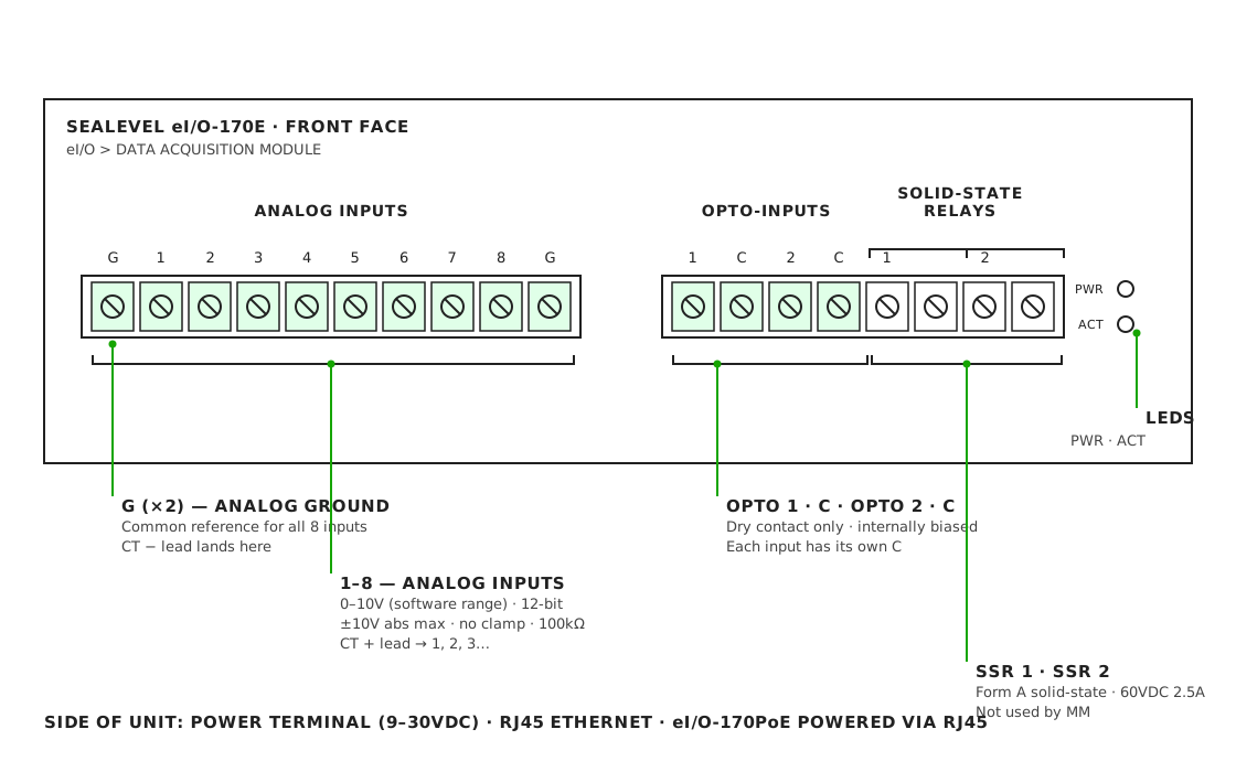
Eight analog inputs (func: 4, registers 0–7) and two dry-contact Opto inputs (func: 2,
inputs 0–1). Each Opto has its own C, and both are internally biased — never apply
external voltage. Default IP is 192.168.42.253.
Full terminal table and notes: Sealevel Terminal Reference.
T-02 — WISE-4050/LAN
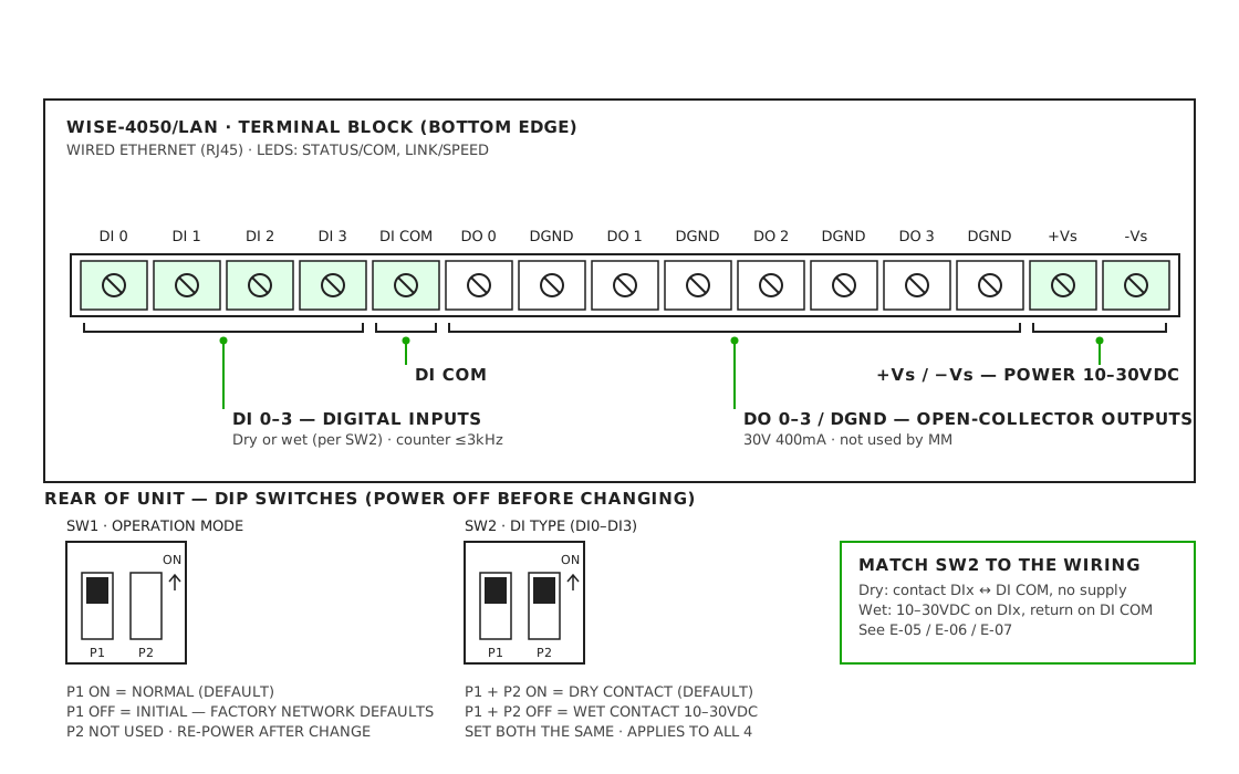
Four discrete inputs (func: 2, inputs 0–3), each also readable as a hardware counter
(func: 3, holding registers 0–3). DI COM is shared, so sourcing and sinking signals
cannot be mixed on one module, and SW2 sets all four inputs wet or dry together.
Default IP is 192.168.1.1, login root / 00000000.
Full terminal table and notes: WISE-4050/LAN.
T-03 — WISE-4050
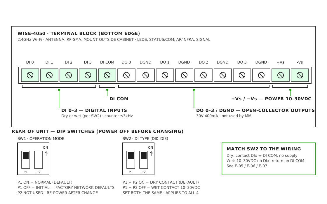
Identical terminals, switches and Modbus map to the LAN model — only the radio differs. It
boots in AP mode (SSID WISE-4050-XXXXXX); switch it to Infrastructure mode to join
the shop Wi-Fi. Fit an antenna extension so the antenna sits outside the steel cabinet.
Full notes: WISE-4050 wireless.
T-04 — WISE-4012

Four universal analog inputs rather than discrete inputs, which makes this the one WISE that accepts a 0–10V current transducer directly. Its dry-contact DI mode samples at only 2Hz per channel — fine for slow states, useless for part-count pulses.
Full terminal table and notes: WISE-4012.
Module Power
E-01 — I/O Module Power

- Preferred source: the same 24VDC supply that drives the signals you monitor. One 0V reference avoids ground offsets and low-voltage alarms.
- Load is about 0.1A per module. Keep the total supply load under 80% of its rating.
- Protect the tap with a 0.5–1A supplementary fuse or MCB, sized to the conductor.
- DC only — Sealevel accepts 9–30VDC, WISE 10–30VDC. Never 24VAC.
- PoE removes field power on the eI/O-170PoE only. WISE has no PoE input.
- Use one source per module. Never parallel two supplies.
Sealevel Wiring Patterns
The three patterns that cover almost every Sealevel install. Each one has a worked adapter script on the Sealevel page.
E-02 — Analog Current Transducer to the Analog Inputs

- Clamp the CT around one phase conductor between the drive and the motor, arrow toward the load.
- Range switch: pick the lowest range above the motor's normal running current. Output
is
10V × amps ÷ range. - Analog inputs have no overvoltage clamp — never land a 24V signal on one.
- Scaling: 4096 counts = 10V, so divide counts by 409.6.
Full notes and script: Analog Current Transducer.
E-03 — Dry Contacts to the Opto Inputs

- The module supplies the sensing current (~12mA through 330Ω). Opto n shorted to its own C reads 1.
- The source must be voltage-free: spare N.O. relay contacts, limit switches, or a CT switch output.
- Never apply external voltage to Opto or C.
- Two discrete inputs only. If you need more, use a WISE-4050.
Full notes and script: Dry Contacts to the Opto Inputs.
E-04 — Interposing Relays for Voltage Signals

- Any signal that carries voltage needs a relay on Sealevel — 24VDC, 24VAC or 120VAC.
- Match the coil voltage to the circuit and wire it in parallel with the existing load.
- DC coils need a flyback diode, cathode to +. AC coils need RC or varistor suppression.
- Piggyback option: parallel a coil across A1/A2 of a contactor that already marks the event.
Full notes and script: Interposing Relays.
WISE Wiring Patterns
Which pattern applies depends on whether the signals carry voltage — and SW2 forces that choice on all four inputs at once. Each has a worked script on the WISE page.
E-05 — Wet Contact (24VDC) Inputs

- Set SW2 OFF (wet) with the module powered down.
- Logic 1 is 10–30VDC at 3mA or more; logic 0 is 0–3VDC. Anything between 3V and 10V is undefined.
- For sourcing (PNP) outputs tie DI COM to the source 0V; for sinking (NPN) tie it to +24V.
- Tap in parallel with the existing load. Do not break the existing circuit.
Full notes and script: Wet Contact Inputs.
E-06 — Dry Contact Inputs

- SW2 ON (dry) is the factory default and the module wets the input internally.
- No external supply in dry mode — applying 24V to an input set for dry contact can damage the module.
- Counter mode is set per input in the web UI and handles up to 3kHz. Use solid-state outputs for fast pulses; mechanical relays bounce.
Full notes and script: Dry Contact Inputs.
E-07 — Relays for AC and Mixed Signals

- WISE wet inputs are DC only. 24VAC and 120VAC always need a relay.
- Because SW2 is all-or-nothing, convert the minority signal type with relays rather than trying to split the module.
Full notes and script: Relays for AC and Mixed Signals.
E-08 — Relay Selection Guide
The single question this answers: does this signal need an interposing relay, or can it land on the module directly?
| Signal | Typical source | Sealevel eI/O-170E | WISE-4050(/LAN) | Sheet |
|---|---|---|---|---|
| Dry contact | Spare M-code relay, limit switch | Direct — Opto n ↔ its C | Direct — DIx ↔ DI COM, SW2 ON | E-03, E-06 |
| 24VDC sourcing (PNP) | PLC output, 24V stack light, Brother XTO (orange) | Relay — 24VDC coil | Direct — wet, SW2 OFF, DI COM → 0V | E-04, E-05 |
| 24VDC sinking (NPN) | NPN PLC output, Brother XTO (gray) | Relay — coil from +24V to output | Direct — wet, SW2 OFF, DI COM → +24V | E-05 |
| 5–9VDC logic | TTL / 5V sensor outputs | Relay | Relay — below the 10V logic-1 threshold | — |
| 24VAC / 120VAC / 240VAC | Stack lights, contactor coil circuits | Relay — AC coil, matched voltage | Relay — AC coil, matched voltage | E-04, E-07 |
| Above 30VDC | 48V hydraulic or legacy controls | Relay | Relay | — |
| Analog CT, 0–10V | Spindle or axis motor current | Direct — Analog n ↔ Analog G | WISE-4050: not supported. WISE-4012: direct — Vn+ / Vn− | E-02 |
| CT with switch output | Current switch, adjustable trip | Direct — Opto n ↔ its C | Direct — dry, SW2 ON | E-03, E-06 |
| High-speed pulse (>10Hz) | Encoder, prox on a fast line | Not recommended | Direct — counter mode, no mechanical relay | E-06 |
| Wet and dry on one module | Mixed machine signals | Wet signals relayed (above) | Relay the minority type — SW2 sets all 4 | E-07 |
If the signal has voltage on it and the input expects a contact — or the voltage is outside the input's range — add a relay.
Interposing relay specification
| Coil | Match the signal voltage and type — 24VDC, 24VAC or 120VAC |
| Contact | N.O. (SPDT acceptable). Gold-flashed or bifurcated for ≤12mA switching |
| Isolation | ≥2.5kV coil-to-contact, rated for the control voltage |
| Suppression | DC — flyback diode. AC — RC or varistor |
| Form | DIN-rail slim interface relay with LED, e.g. Phoenix Contact PLC-RSC, Finder 38 series, IDEC RV8H |
| Timing | ~5–15ms operate. Fine for part-count pulses ≥100ms. Use an SSR or WISE counter mode for faster signals |
Complete Installs
E-09 — CNC Lathe — Spindle CT and Barfeeder Part Count

Hardware: Sealevel eI/O-170E
- Execution: CT1 clamped on one main-spindle phase, output to Analog 1 / Analog G. ACTIVE when Analog 1 exceeds about 1.15V, with a 10-second off-delay.
- Part count: the barfeeder 24VDC output drives CR1 — A1 from the signal, A2 to 0V. CR1's N.O. contact goes to Opto 1 and its C.
- The relay is required. Opto inputs accept contacts only. Never land the 24VDC barfeeder signal on an Opto or an analog input.
- Count on the rising edge. One bar advance is one part unless the program cuts several parts per bar — scale it in the script, or count on part eject instead.
- The pulse should hold for 100ms or longer so the poll catches it.
- Opto 2 is spare — a second relay could bring in an alarm signal.
Adapter script
version: 2
unit-id: 1

registers:
  spindle-raw:
    address: 0 # Analog 1 -> input register 0
    func: 4
    type: int16

coils:
  barfeed-pulse:
    address: 0 # CR1 N.O. -> Opto 1 -> discrete input 0
    func: 2

variables:
  ct-voltage-int:
    - source: spindle-raw / 409.6

  ct-voltage:
    - source: ct-voltage-int
    - resample: 0.5
    - min-delta: 0.1

  execution:
    - source: ct-voltage-int > 1.15
    - off-delay: 10
    - state:
        - ACTIVE: this
        - READY: true

  part-count:
    - source: barfeed-pulse
    - rising-edge
    - count

data-items:
  - execution
  - part-count
  - ct-voltage
E-10 — Punch Press — High-Speed Stroke Count and Execution

Hardware: WISE-4050 or WISE-4050/LAN
- Use WISE, not Sealevel. WISE counts DI0 in hardware at up to 3kHz. Sealevel's Opto inputs are polled and will miss strokes at press rates.
- Use a solid-state relay. A press runs millions of strokes; mechanical relays bounce and wear out. Choose a DC-in/DC-out SSR rated for 1kHz or better, with off-state leakage under 0.1mA.
- SSR output is polarity-sensitive: 13+ to DI0, 14− to DI COM. On the input side, A1+ comes from the stroke signal and A2− goes to machine 0V.
- Set DI0 to counter mode in the WISE web UI and read it as holding register 0.
- One signal, two data items. Part count is the counter increase; execution is ACTIVE while the counter increments, held by an off-delay longer than the slowest normal gap between strokes.
- DI1–DI3 stay in dry mode along with DI0. Relay any other voltage signal.
Adapter script
version: 2
unit-id: 1
scan-interval: 0.25

registers:
  part-count:
    address: 0 # DI0 counter register
    func: 3
    type: uint16

variables:
  counter-changed:
    - source: part-count
    - value-increase

  execution:
    - source: counter-changed
    - off-delay: 10 # longer than the slowest normal gap between strokes
    - state:
        - ACTIVE: this
        - READY: true

data-items:
  - execution
  - part-count
Brother SPEEDIO — XTO External Outputs
Brother CNCs expose machine states and M-code pulses on an XTO external output terminal block, which wires into the I/O kit when the control cannot share data over Ethernet. The three drawings below differ only in how the XTO's 24VDC outputs reach the module.
Assign the signals first, in User Parameter 6 (External Out Signal). The usual pair is
GRN (code 53) for execution and M30/1 (code 10) for part count; the drawings show
CNTUP (code 56) as the count signal, which is the alternative where the control's own
counter already tracks your process. See
Brother A & B Series for
locating the XTO, the full signal list and the adapter scripts.
| Your hardware | Drawing | Relay needed? |
|---|---|---|
| WISE-4050 or WISE-4050/LAN | E-11 | No |
| Sealevel, XTO board set to PNP | E-12 | Yes — one per signal |
| Sealevel, CNXTO connector (NPN) | E-13 | No |
E-11 — Brother XTO Direct to WISE (Wet Inputs)

Hardware: WISE-4050 or WISE-4050/LAN
- XTO terminals 103–110 are 24VDC transistor outputs — a wet signal, not a dry contact.
- Set SW2 to wet (P1 + P2 OFF) with the module powered down, and land DI COM on IOG (terminal 111 or 112).
- No relay needed. WISE wet inputs accept 10–30VDC.
- If the IO PCB is set to NPN (sink), land DI COM on IO24 (terminal 101) instead. The output then pulls the DI low to read 1 — a wet input works in either polarity.
- Power the WISE from the MachineMetrics 24VDC supply (E-01), not from IO24.
- Confirm the PNP/NPN setting and terminal numbers on the machine's IO print (on a TC-R2B, drawing 670532-001).
E-12 — Brother XTO to Sealevel Through Relays

Hardware: Sealevel eI/O-170E, plus two 24VDC interposing relays
- Sealevel Opto inputs are dry only. The 24VDC XTO outputs must drive a relay — never land them on Opto or C.
- CR1 and CR2 are 24VDC coil interface relays with low-level (gold) N.O. contacts. Use relays with built-in suppression, or fit D1/D2 with the cathode to the output side.
- Return the coils to IOG (111/112), and keep total coil current within the XTO output rating in the Brother manual.
- If the IO PCB is set to NPN (sink), take coil A2 to IO24 (101) and put the diode cathode to IO24.
- Sealevel polls its Opto inputs, so it can miss very short count pulses. On fast cycle times use E-11 instead.
E-13 — Brother CNXTO (NPN) Direct to Sealevel

Hardware: Sealevel eI/O-170E, no relays
Some SPEEDIO machines expose a CNXTO connector (XHP-10) whose outputs are NPN (sinking). An NPN output switched to 0V behaves exactly like a contact closure, so it goes straight to an Opto input.
- Output ON switches the Opto pin to IOG — a closed contact, with Sealevel sourcing the loop current.
- Polarity matters: Opto n to the output pin, Opto C to IOG (pin 2). Both C terminals can share IOG.
- Leave pin 1 (IO24) unconnected. Never land 24V on Opto or C.
- Pull-up check before you trust it: with the wires off and the output OFF, measure P0103 to IOG. If it reads 24V there is an internal pull-up and you must use E-12 instead.
- CNXTO can stay NPN even when the main XTO board is set to PNP — confirm both the polarity and the pinout on the machine's IO print.
Machine-Specific Integrations
Haas CNC Machines (Pre 2001)
Recommended Configuration:
- Hardware: Sealevel eI/O-170E
- AN1: Spindle CT (analog 0-10V)
- Opto 1: Part count relay or coolant contactor
Adapter Script:
version: 2
unit-id: 1

registers:
  spindle-raw:
    address: 0 # AN1
    func: 4
    type: int16

coils:
  part-signal:
    address: 0
    func: 2 # Read Discrete Inputs

variables:
  # Spindle monitoring (intermediate conversion)
  spindle-voltage-int:
    - source: spindle-raw / 409.6

  # Cleaned version for data output
  spindle-voltage:
    - source: spindle-voltage-int
    - resample: 0.5
    - min-delta: 0.1

  execution:
    - source: spindle-voltage-int > 1.15
    - off-delay: 10
    - state:
        - ACTIVE: this
        - READY: true

  part-count:
    - source: part-signal
    - rising-edge
    - count

data-items:
  - execution
  - part-count
  - spindle-voltage
Citizen/Miyano Lathes
Recommended Configuration:
- Hardware: Sealevel eI/O-170E
- AN1: Main spindle CT
- AN2: Sub spindle CT (if applicable)
- Opto 1: Work count relay
Adapter Script:
version: 2
unit-id: 1

registers:
  main-spindle-raw:
    address: 0 # AN1
    func: 4
    type: int16

  sub-spindle-raw:
    address: 1 # AN2
    func: 4
    type: int16

coils:
  work-count:
    address: 0
    func: 2 # Read Discrete Inputs

variables:
  # Convert CTs to voltage (intermediate)
  main-voltage-int:
    - source: main-spindle-raw / 409.6

  sub-voltage-int:
    - source: sub-spindle-raw / 409.6

  # Cleaned versions for data output
  main-voltage:
    - source: main-voltage-int
    - resample: 0.5
    - min-delta: 0.1

  sub-voltage:
    - source: sub-voltage-int
    - resample: 0.5
    - min-delta: 0.1

  # Active if either spindle running
  execution:
    - source: main-voltage-int > 1.0 or sub-voltage-int > 1.0
    - off-delay: 10
    - state:
        - ACTIVE: this
        - READY: true

  part-count:
    - source: work-count
    - rising-edge
    - count

data-items:
  - execution
  - part-count
  - main-voltage
  - sub-voltage
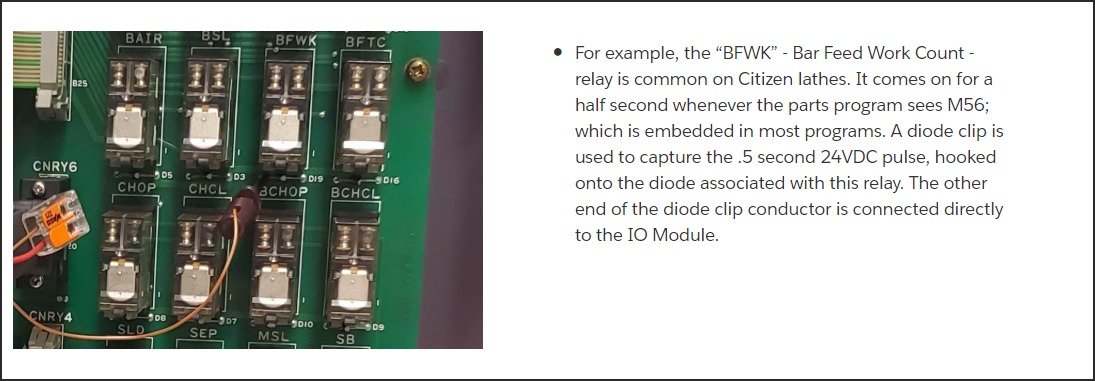
Part Count — BFWK Bar Feed Work Count Relay (Citizen/Cincom)
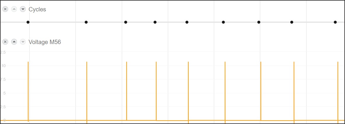
On Citizen Cincom lathes, the BFWK relay (Bar Feed Work Count) fires for approximately 0.5 seconds whenever the parts program executes M56. A diode clip captures the 24VDC pulse from the relay's back-EMF diode and connects directly to the I/O module.
Mori Seiki / DMG MORI Machines
Part Count — Coolant Pump Contactor (Dry Contact Method)
On Mori Seiki and DMG MORI machines, the coolant pump contactor (often labeled KM63) provides a reliable set of dry Normally Open (NO) contacts for part counting. Because the contacts are dry (no voltage present), connect the VS pin (5VDC) of the I/O module to one side, and the other side to the AIN input.
Add this G-code string at the end of each parts program to pulse the coolant pump for part counting:
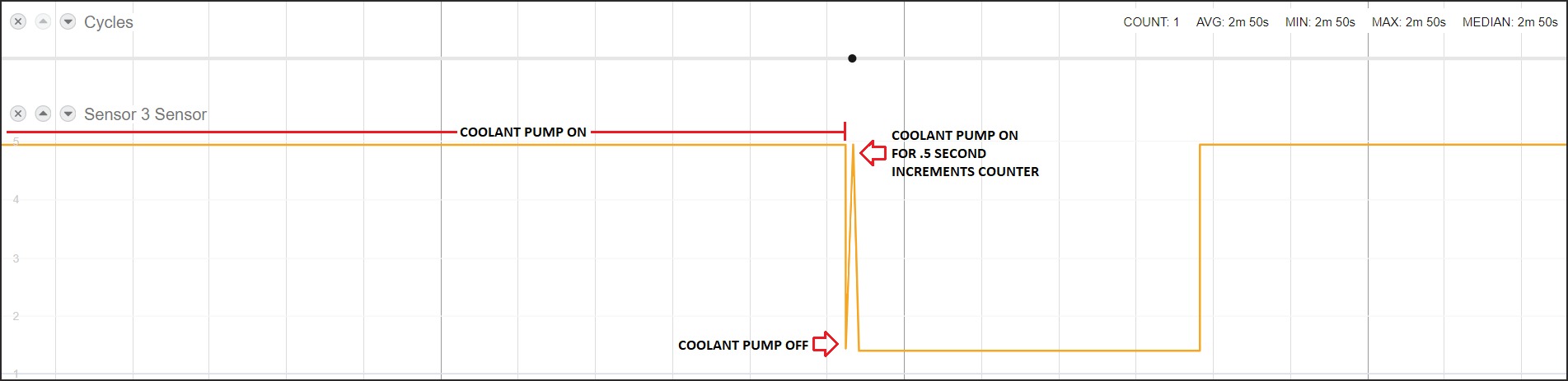
M8;   (coolant on)
G4X.5; (.5 second dwell)
M9;   (coolant off)
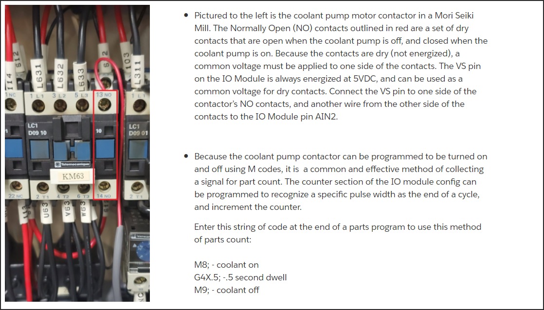
VS and AIN are LabJack terminals. On a Sealevel eI/O-170E the contactor's dry auxiliary contact wires between Opto 1 and its own C with no external supply — see Dry Contacts to the Opto Inputs. On a WISE-4050 it goes between DI0 and DI COM with SW2 ON.
Adapter script
version: 2
unit-id: 1

coils:
  coolant-contact:
    address: 0 # KM63 N.O. aux -> Opto 1 (Sealevel) or DI0 (WISE)
    func: 2

variables:
  part-count:
    - source: coolant-contact
    - rising-edge
    - count

data-items:
  - part-count
The 0.5-second M8 / G4X.5 / M9 pulse is short, so keep the module's poll fast enough to
see it. If coolant also runs during cutting, the long "on" period will be counted as a
part — see Example 6: Coolant Pulse Method for the pulse-width
filtering that separates a deliberate count pulse from normal coolant use.
Part Count — Chip Conveyor or Spare M-Code Contactor
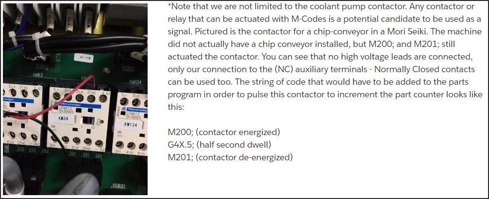
Any M-code-actuated contactor is a candidate. The chip conveyor contactor (shown below on a Mori Seiki) may not have a chip conveyor installed, but M200/M201 still actuate the contactor — giving you a free normally-closed (NC) contact that can be used as a part count signal.
Part Count — Spare M-Code Relays (HMCs)
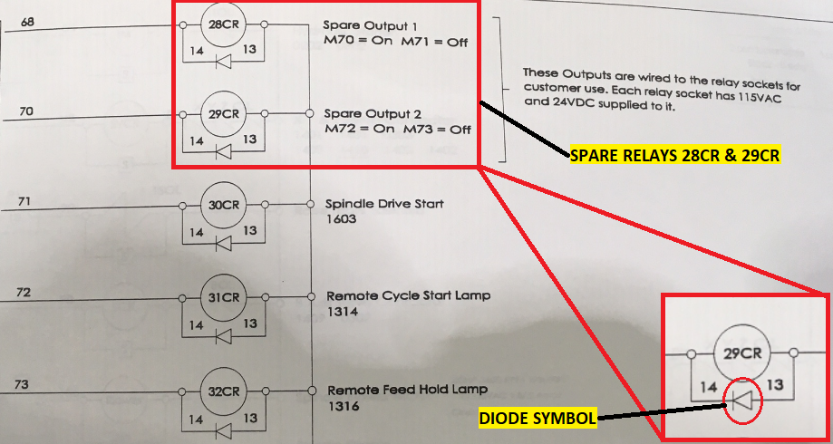
Horizontal machining centers (HMCs) often have spare output relays (e.g., 28CR / 29CR actuated by M70/M71) pre-wired to relay sockets with 24VDC already supplied. The ladder diagram shows the diode symbol indicating the coil polarity — hook a diode clip to the appropriate relay's diode legs.
Work Ejector / Unloader Part Count (Mazak, Okuma, and others)
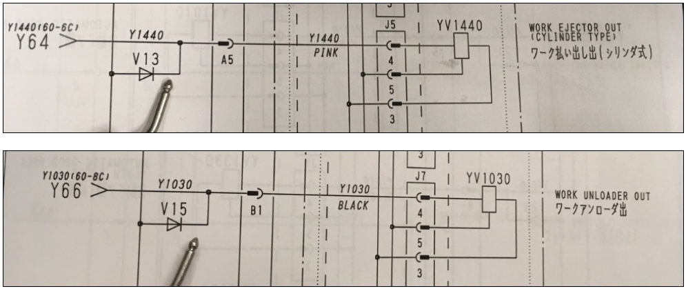
Some machining centers count parts by monitoring two signals simultaneously: the Work Ejector output (Y1440) and the Work Unloader output (Y1030). A part is counted only when both signals are active at the same time.
Step 1: Find Ejector and Unloader signals in the ladder diagram
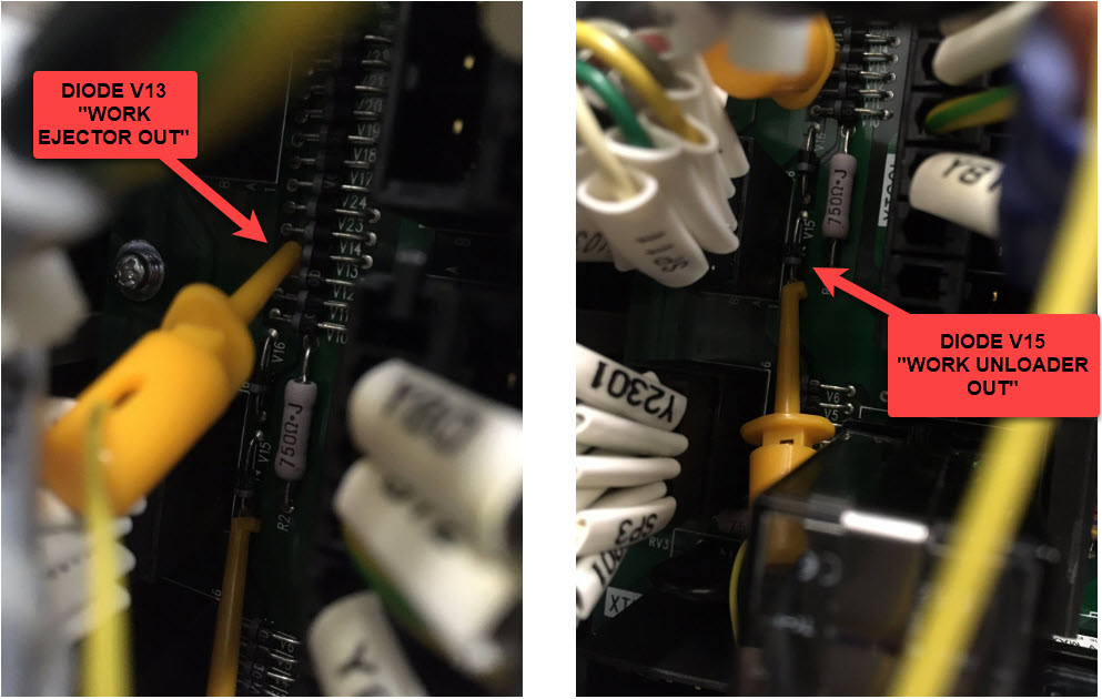
Step 2: Identify and tap the diodes on the PCB
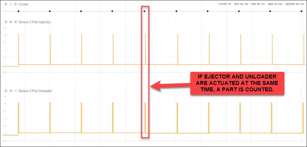
Step 3: Verify in MachineMetrics
Wire the ejector to AIN1 (Sensor 2) and the unloader to AIN2 (Sensor 3). In the adapter script, count a part only when both sensors are simultaneously active.
Adapter script
version: 2
unit-id: 1

coils:
  ejector:
    address: 0 # Y1440 Work Ejector Out
    func: 2
  unloader:
    address: 1 # Y1030 Work Unloader Out
    func: 2

variables:
  # Count only when both outputs are active at the same time.
  part-complete:
    - source: ejector and unloader

  part-count:
    - source: part-complete
    - rising-edge
    - count

data-items:
  - part-count
  - ejector
  - unloader
Send both raw signals as data items while commissioning. If the two outputs never overlap in the timeline, they are sequential rather than simultaneous on your machine, and you should count on the ejector alone.
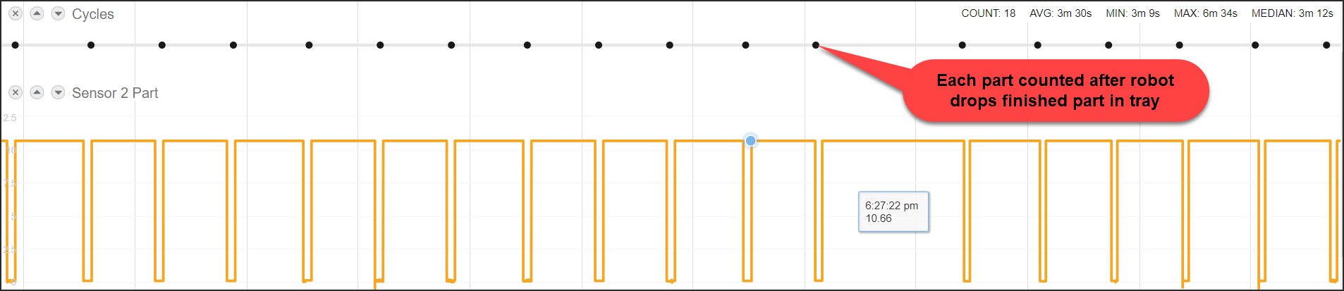
For robot-unloaded cells, the robot's part-drop signal (e.g., a relay when the finished part is placed in the tray) can be used as a single-sensor part count:
Yaskawa Robot Integration
Yaskawa DX200 and similar robot controllers expose discrete I/O through CN308 / CN309 / CN306 / CN307 terminal blocks. The I/O module connects directly to the appropriate terminal.
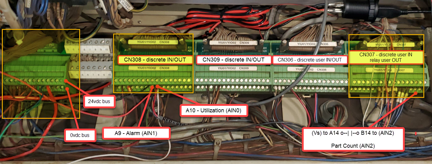
Robot controller outputs usually carry 24VDC, so on a Sealevel each one needs an interposing relay. A WISE-4050 can take them directly in wet mode.
Adapter script
version: 2
unit-id: 1

coils:
  running:
    address: 0 # A10 - robot running
    func: 2
  alarm-signal:
    address: 1 # A9 - alarm
    func: 2
  part-pulse:
    address: 2 # A14/B14 - part complete
    func: 2

variables:
  execution:
    - state:
        - INTERRUPTED: alarm-signal
        - ACTIVE: running
        - READY: true

  part-count:
    - source: part-pulse
    - rising-edge
    - count

  alarm:
    - source: alarm-signal

data-items:
  - execution
  - part-count
  - alarm

conditions:
  system:
    message: Robot is in alarm
    value:
      FAULT: alarm
Press Brakes
Press brakes are monitored by detecting the Ram Down signal — the output that fires each time the ram completes a stroke (one stroke = one part bend).
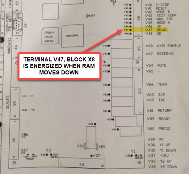
Step 1: Locate the Ram Down terminal in the ladder diagram
The Ram Down signal is typically labeled DOWN or V47 in the press's schematic:
Step 2: Find the physical relay or terminal block
Step 3: Identify the Utilization signal (if using a separate input)
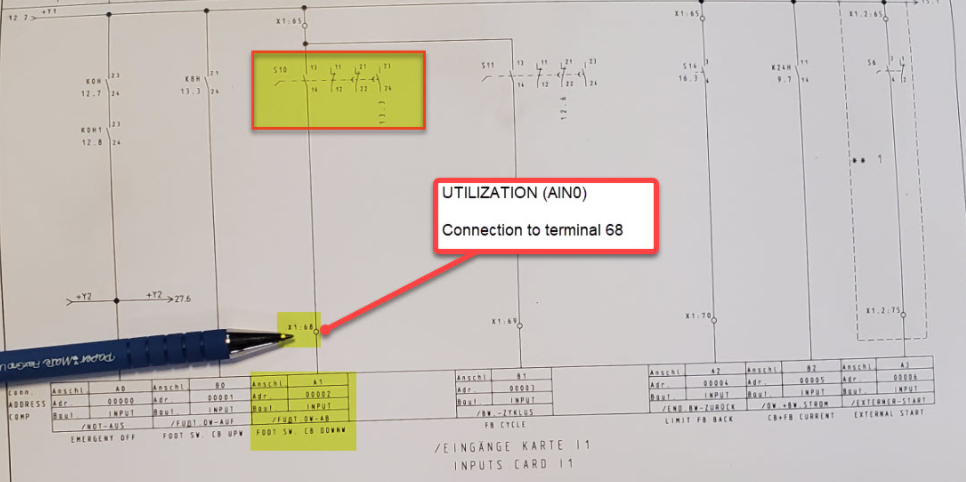
For machines where a separate Utilization (AIN0) signal is desired (e.g., foot switch or "Press Active" state), identify the corresponding input card terminal:
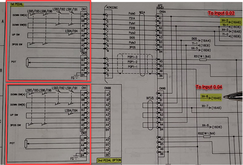
For machines with foot pedals, the Down Switch signals route through CNs and connect to the I/O module inputs:
Step 4: Verify Ram Down signal in MachineMetrics

Step 5: Configure the adapter script
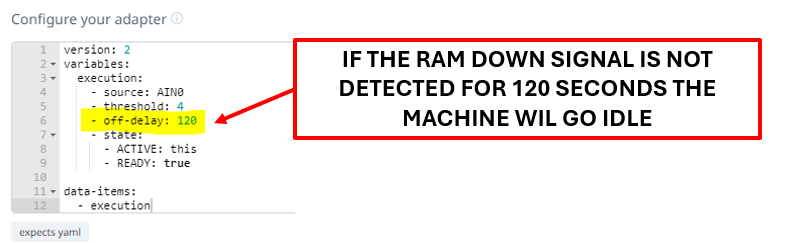
Because press brakes cycle very rapidly, set an off-delay (e.g., 120 seconds) so the machine doesn't flip to idle between strokes:
version: 2
unit-id: 1

coils:
  ram-down:
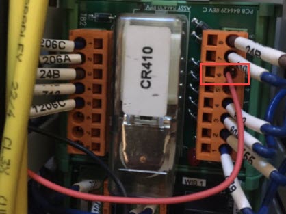
    address: 0 # V47 via CR410 relay contact
    func: 2
  foot-switch:
    address: 1 # X1:68 "Foot SW CB DOWN" - optional
    func: 2

variables:
  part-count:
    - source: ram-down
    - rising-edge
    - count

  execution:
    - source: ram-down
    - off-delay: 120 # operators reposition between bends
    - state:
        - ACTIVE: this
        - READY: true

data-items:
  - execution
  - part-count
One stroke is one bend, not one finished part. If a part takes several bends, divide in the
script or count on a downstream signal instead. Where a foot switch is wired, use
foot-switch for execution and keep ram-down purely for counting — the operator is
working at the machine even between strokes.
Injection Molding Machines
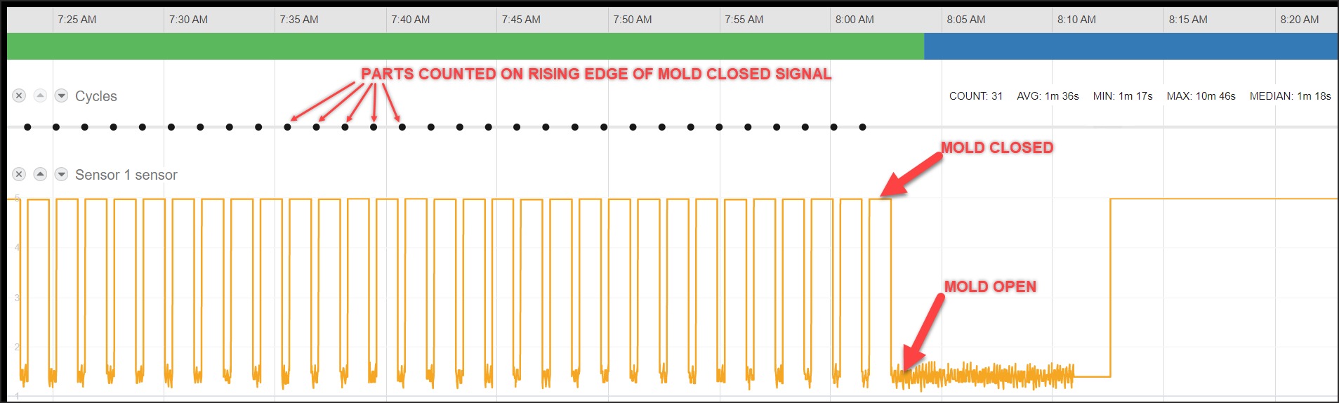
Injection molding machines are monitored through the mold-closed output — a signal that fires each time the mold closes (one close = one cycle, one part). Parts are counted on the rising edge of the mold-closed signal.
Adapter script
version: 2
unit-id: 1

coils:
  mold-closed:
    address: 0
    func: 2

variables:
  part-count:
    - source: mold-closed
    - rising-edge
    - count

  execution:
    - source: mold-closed
    - off-delay: 300 # longer than the slowest normal cycle
    - state:
        - ACTIVE: this
        - READY: true

data-items:
  - execution
  - part-count
A multi-cavity mold produces several parts per close. Scale the count in the script, or record the cavity count against the job so the shot count can be converted downstream. See Example 8: Injection Molding Machine for the multi-cavity variant.
Related Articles
- Adapter Scripts — the full script library
- Sealevel and WISE — module wiring patterns and terminal references
- Troubleshooting — when a wired signal does not appear