Brother A & B Series
A and B Series controls cannot share data over Ethernet, so they connect through the I/O kit instead. Machine states and an M-code pulse are taken from the control's external output terminals and wired into an I/O module, which reports active/idle state, part count and alarm state.
That is fewer data items than the Ethernet methods used by the C Series and D Series, but enough for utilization and part counting. It is also the fallback for a C or D Series machine whose Ethernet port is unusable, and the right choice whenever you specifically want physical signal monitoring — a stack light or an M-code — rather than data read from the control.
What you wire: the terminals on the control's XTO board (External Terminal Output), found on a circuit board inside the electrical cabinet, into the discrete inputs of the I/O module. There is no network connection to the control at all.
Step 1 — Locate a Usable Power Source
The MachineMetrics I/O hardware requires 24VDC, sourced from the machine's wiring. All Brother CNCs have a 24VDC power supply capable of powering auxiliary hardware. To avoid voltage alarms, power the MachineMetrics hardware from the same power source as the signals you will be pulling from the machine's circuitry.
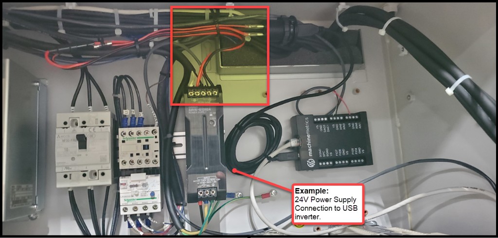
Example: 24VDC power supply connection to the USB inverter. Layout will vary by machine model.
Step 2 — Locate the External Output Terminal Block (XTO)
Brother CNCs are equipped with a block of terminals that can be programmed to energize in conjunction with specific machine states or M-codes. This terminal block is called the XTO (External Terminal Output) and is located on a circuit board inside the electrical cabinet.
Finding the XTO:
- Look for circuit boards labeled XTO — do not confuse with XTI (External Terminal Input)
- There are typically two XTO terminal blocks on the same board:
- Orange block (PNP) — outputs 24VDC when the assigned signal is active ✅ Preferred
- Gray block (NPN) — opens 0V when active (requires a relay to pass signal to the I/O module)
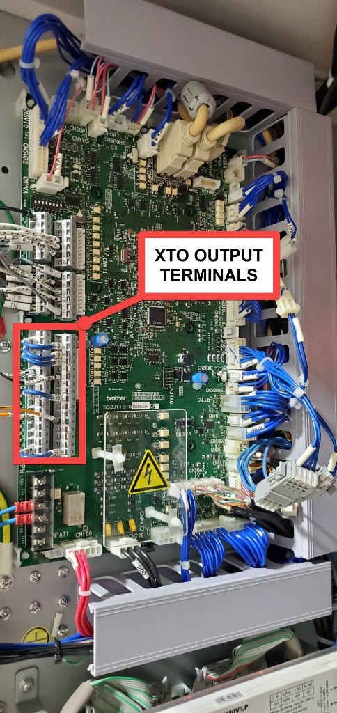
XTO terminal block location inside the Brother electrical cabinet.
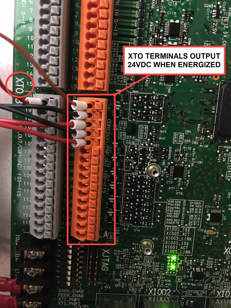
The orange (PNP) XTO terminals output 24VDC when active. Both the orange and gray blocks are XTO terminals numbered consistently.
Identify 2–3 unoccupied terminals on the XTO block that you will program in the next step.
Step 3 — Program the XTO Outputs
With unoccupied terminals identified, navigate to the External Output Signal programming screen on the controller.
Navigation path:
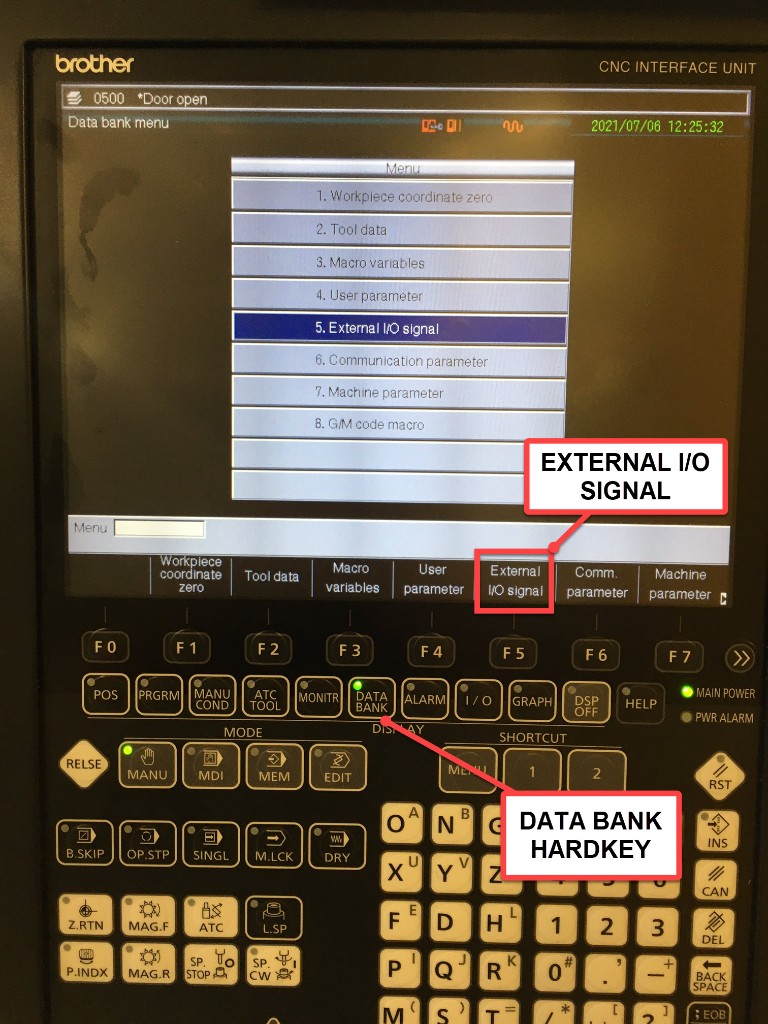
- Press the DATA BANK hard key on the controller
-
If the menu shows "External I/O Signal" as a softkey, press it directly.
If the menu instead shows "User Parameter", press that softkey first:
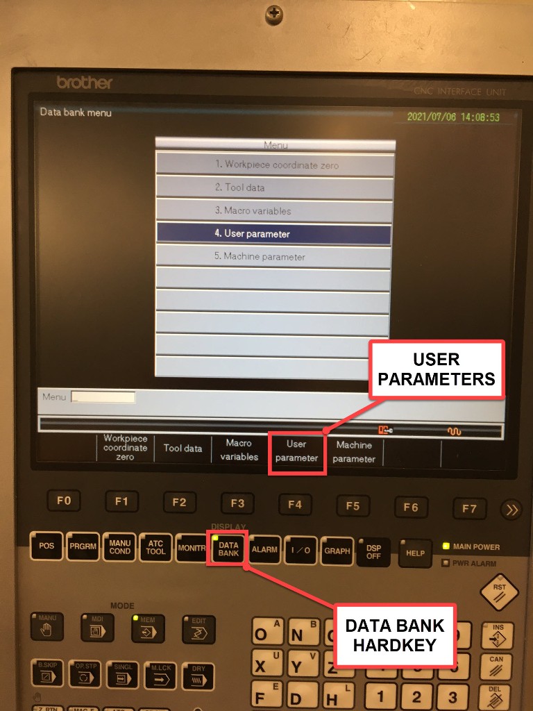
- From the User Parameters screen, if "External I/O Signal" is not visible, press Next Menu:
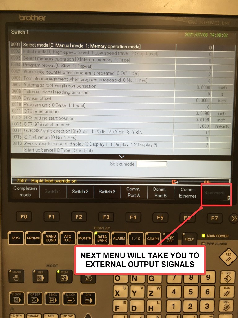
- You will arrive at the External Output Signal screen. The lower half of the screen lists signal abbreviations (machine states and M-codes). The upper half shows the terminal assignments.
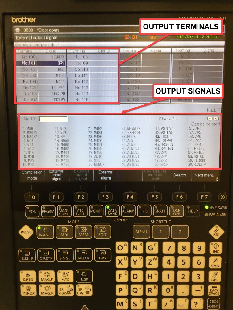
Recommended signal assignments:
| Terminal | Signal | Code | Purpose |
|---|---|---|---|
| XTO terminal (e.g., No.333) | GRN | 53 | Green stack light — machine active state |
| XTO terminal (e.g., No.334) | M30/1 | 10 | Program end pulse — part count trigger |
| XTO terminal (e.g., No.335) | ALM | 27 | Alarm state |
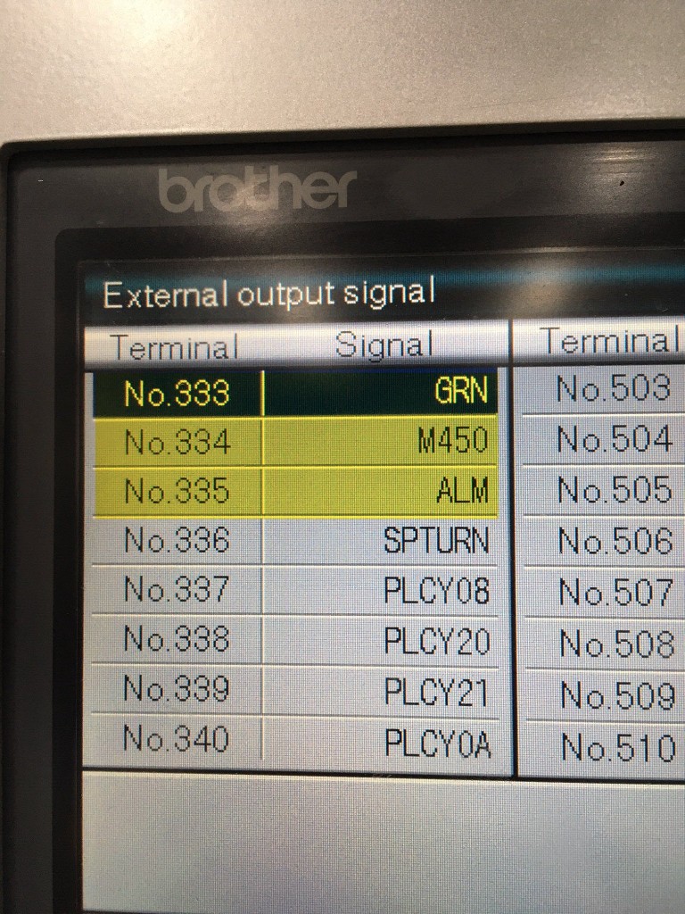
Signal notes:
GRN(53) — Energizes whenever the green stack light signal is active, whether or not a physical light is installed. This is the standard execution signal and the most reliable indicator of machine activity.M30/1(10) — Pulses whenM30(program end) executes on pallet/path 1. This is the standard part-count signal: it needs no program edits, because every program already ends inM30. UseM30/2(code 11) for the second pallet on a two-pallet machine.ALM(27) — Energizes when the machine is in an alarm state.
Choosing a part-count signal
M30/1 is the default choice, but it counts one part per program end. Two alternatives
are worth knowing:
| Signal | Code | When to use it |
|---|---|---|
M30/1 | 10 | Default. One program run = one part. No program changes needed |
CNTUP | 56 | The control's counter-up signal. Use it when the machine's own part counter already tracks your process correctly |
M450 | 49 | A spare M-code with no machine function. Use it when one program produces several parts, or when the count must fire somewhere other than program end — add M450; to the program at the point of part completion |
All three wire identically. Only the code you assign to the terminal changes, so you can switch later without touching the wiring or the adapter script.
Available signals
Terminals accept any of 94 common signal codes, plus NC-only and Conversation-only ranges. The full list is in the control's manual under User Parameter 6 (External Out Signal):
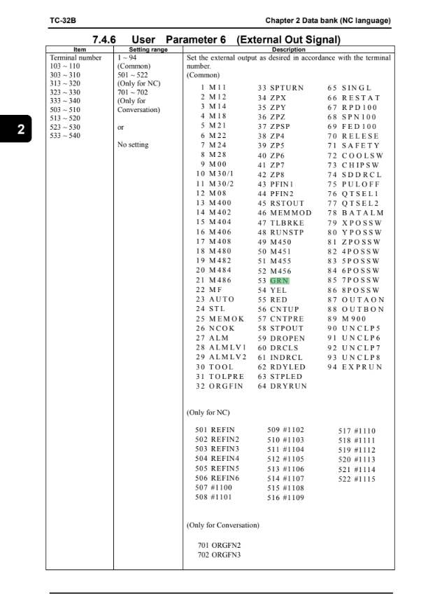
Beyond the three above, the codes most often useful to MachineMetrics are:
| Code | Signal | Meaning |
|---|---|---|
| 11 | M30/2 | Program end, pallet/path 2 |
| 23 | AUTO | Control is in automatic mode |
| 24 | STL | Cycle start lamp — program is running |
| 54 | YEL | Yellow stack light |
| 55 | RED | Red stack light |
| 94 | EXPRUN | Program is executing |
After assigning signals to XTO terminals, be sure to save before exiting. The save method varies by controller — look for a "Write" or "Save" softkey, or press INPUT to confirm each entry.
Step 4 — Wire XTO Terminals to the I/O Module
How you wire the XTO depends on the I/O module and on whether the board is set to PNP or NPN. Three patterns cover every case.
They are reference wiring drawn from the manufacturer datasheets, not a wiring diagram for your machine. Verify every connection against the machine's own electrical prints before you install, and confirm the PNP/NPN setting and terminal numbers on the machine's IO print.
Which pattern applies
| Your hardware | Pattern | Relay needed? |
|---|---|---|
| WISE-4050 or WISE-4050/LAN | E-11 | No |
| Sealevel eI/O-170E, XTO board set to PNP | E-12 | Yes — one per signal |
| Sealevel eI/O-170E, CNXTO connector (NPN) | E-13 | No |
The XTO PNP outputs supply 24VDC when active. That matters because the Sealevel Opto inputs are dry-contact only — they supply their own sensing current and must never have external voltage applied. A WISE-4050 accepts 24VDC directly in wet mode, which is why it needs no relays.
E-11 — XTO direct to WISE (wet inputs)

- XTO terminals 103–110 are 24VDC transistor outputs — a wet signal, not a dry contact.
- Set SW2 to wet (P1 + P2 OFF) with the module powered down. Land DI COM on IOG (terminal 111 or 112).
- No relay needed. WISE wet inputs accept 10–30VDC.
- If the IO PCB is set to NPN (sink) instead, land DI COM on IO24 (terminal 101). The output then pulls DI 0 / DI 1 low to read 1 — a WISE wet input works in either polarity.
- Power the WISE from the MachineMetrics 24VDC supply, not from IO24.
E-12 — XTO to Sealevel through relays

- Sealevel Opto inputs are dry only. The 24VDC XTO outputs must drive a relay — never land them on Opto or C.
- CR1 and CR2 are 24VDC coil interface relays with a low-level (gold) N.O. contact. Use relays with built-in suppression, or fit D1/D2 with the cathode to the output side.
- Return the coils to IOG (111/112), and keep the total coil current within the XTO output rating given in the Brother manual.
- If the IO PCB is set to NPN (sink), take coil A2 to IO24 (101) and put the diode cathode to IO24.
- Sealevel polls its Opto inputs, so it can miss very short count pulses. On fast cycle times use the WISE pattern above.
E-13 — CNXTO (NPN) direct to Sealevel

Some SPEEDIO machines expose a CNXTO connector (XHP-10) whose outputs are NPN (sinking). An NPN output switched to 0V behaves exactly like a contact closure, so it wires straight to a Sealevel Opto input with no relay at all.
- Output ON switches the Opto pin to IOG — a closed contact, with Sealevel sourcing the loop current.
- Polarity matters: Opto n to the output pin, Opto C to IOG (pin 2). Both C terminals can share IOG.
- Leave pin 1 (IO24) unconnected. Never land 24V on Opto or C.
- Pull-up check before you trust it: with the wires off and the output OFF, measure P0103 to IOG. If it reads 24V there is an internal pull-up, and you must use the relay pattern (E-12) instead.
- CNXTO can remain NPN even when the main XTO board is set to PNP — confirm both the polarity and the pinout on the machine's IO print.
Step 5 — Adapter Script
Which script you use depends on the module, because the signals arrive on different kinds of input.
WISE-4050 (E-11)
The four DI channels read as discrete inputs, so all three signals fit on one module with a channel to spare.
version: 2
unit-id: 1

coils:
  green-light:
    address: 0 # DI0 — GRN (53)
    func: 2
  part-pulse:
    address: 1 # DI1 — M30/1 (10)
    func: 2
  alarm-signal:
    address: 2 # DI2 — ALM (27)
    func: 2

variables:
  execution:
    - source: green-light
    - off-delay: 10
    - state:
        - ACTIVE: this
        - READY: true

  part-count:
    - source: part-pulse
    - rising-edge
    - count

  alarm:
    - source: alarm-signal

data-items:
  - execution
  - part-count
  - alarm

conditions:
  system:
    message: Machine is in fault state
    value:
      FAULT: alarm
Sealevel through the Opto inputs (E-12 and E-13)
Both Sealevel patterns land on the Opto inputs, so they read as dry contacts and the script is the same for either one.
version: 2
unit-id: 1

coils:
  green-light:
    address: 0 # Opto 1 — GRN (53)
    func: 2
  part-pulse:
    address: 1 # Opto 2 — M30/1 (10)
    func: 2

variables:
  execution:
    - source: green-light
    - off-delay: 10
    - state:
        - ACTIVE: this
        - READY: true

  part-count:
    - source: part-pulse
    - rising-edge
    - count

data-items:
  - execution
  - part-count
That is enough for execution and part count, but leaves no room for alarm. To collect alarm
as well, either use a WISE-4050, or relay ALM into an analog input and read it with a
threshold as shown below.
Sealevel with a third signal on an analog input
Where a third signal is needed on a Sealevel, relay it into an analog input and treat
anything above about 3V as a logic HIGH. This variant wires GRN to AN1, ALM to AN2 and
the count pulse to AN3, all through 24VDC relays.
version: 2

registers:
  green-light-raw:
    address: 0 # AN1 — GRN (53)
    func: 4
    type: int16

  red-light-raw:
    address: 1 # AN2 — ALM (27)
    func: 4
    type: int16

  part-count-raw:
    address: 2 # AN3 — M30/1 (10) part count pulse
    func: 4
    type: int16

variables:
  green-voltage:
    - source: green-light-raw / 409.6
    - resample: 0.5
    - min-delta: 0.1

  execution:
    - source: green-light-raw / 409.6
    - threshold: 3
    - off-delay: 10
    - state:
        - ACTIVE: this
        - READY: true

  alarm:
    - source: red-light-raw / 409.6
    - threshold: 3

  part-count:
    - source: part-count-raw / 409.6
    - threshold: 3
    - rising-edge
    - count

data-items:
  - execution
  - part-count
  - green-voltage
  - alarm

conditions:
  system:
    message: Machine is in fault state
    value:
      FAULT: alarm
Script notes:
off-delay: 10holds the ACTIVE state for 10 seconds after the green light drops, which prevents the state flickering during brief tool changesthreshold: 3(analog variant only) treats anything above about 3V as a logic HIGH, appropriate for 24VDC signals read through the 0–10V analog input range. Adjust it if your signals read differently- The
alarmvariable feeds theconditionsblock, so both the data item and the fault condition reflect alarm state - Part count comes from a momentary pulse, so it is always counted on the rising edge. If the count double-increments, the signal is producing more than one edge per part — add
debounceahead ofcount
Related Articles
- Digital I/O Connectivity — I/O hardware, wiring reference and signal types
- Digital I/O Wiring Examples — the full schematic set, including these three Brother drawings
- Brother Connectivity — all Brother series and connection methods