Digital I/O Adapter Scripts
Every Digital I/O install needs an adapter script. The wiring gets a voltage or a contact
state onto a Modbus address; the script turns that into execution, part-count and
anything else MachineMetrics shows.
Adding a Digital I/O machine in MachineMetrics configures the path to your hardware over Modbus/TCP. It does not map inputs, coils and registers to utilization, part count or anything else. You must add an adapter script that interprets your wired signals. Without it the hardware is reachable but no production data appears — the most common reason an I/O install is believed to have failed.
Adding the Device in MachineMetrics
Once your Sealevel or WISE module is physically installed and configured with a static IP, you can add it as a Data Collection Method in MachineMetrics.
Step 1: Open Data Collection Settings
Navigate to Assets → Machines → [Machine] → Settings → Data Collection and click + Add a new Data Collection Method.
Step 2: Select Integration Type
Choose the integration type that matches your hardware:
| Hardware | Integration Type to Select |
|---|---|
| Sealevel eI/O-170E / eI/O-170E-ROHS | Modbus |
| Advantech WISE-4050 / WISE-4050/LAN | Modbus |
| LabJack T4 | Digital IO (T4-Module) |
| LabJack T7 (standard) | Digital IO (T7-Module) |
| LabJack T7 (thermocouple inputs) | Modbus |
| Generic Modbus/TCP device | Modbus |
[digital-io-dropdown-1.png placeholder]
[digital-io-dropdown-2.png placeholder]
[digital-io-dropdown-3.png placeholder]

Step 3: Enter the Connection Address
The format of the Connection Address depends on which integration type you selected:
Modbus-based devices (Sealevel, WISE, Generic Modbus):
Enter both the IP address and the port number, separated by a colon:
[IP address]:[port]
Example:
10.20.112.52:502
Do not enter the IP address alone. If the port is missing, MachineMetrics cannot open a Modbus/TCP connection and the machine will show as offline.
- Standard Modbus port:
502(used by Sealevel and WISE modules unless changed) - To confirm the port: check the device's web interface or documentation
LabJack T4 (T4-Module):
The T4-Module integration uses an older method that does not use Modbus/TCP. Enter the IP address only — do not include a port number.
- ✅ Correct:
10.120.40.88 - ❌ Incorrect:
10.120.40.88:502
Including a port number will cause the connection to fail.
LabJack T7 (T7-Module):
For the standard Digital IO (T7 Module) integration, enter the IP address only — do not include a port number.
- ✅ Correct:
10.120.40.88 - ❌ Incorrect:
10.120.40.88:502
If you are reading thermocouple inputs from a T7, use the Modbus integration type instead and enter both the IP address and port:
- ✅ Correct:
10.120.40.88:502
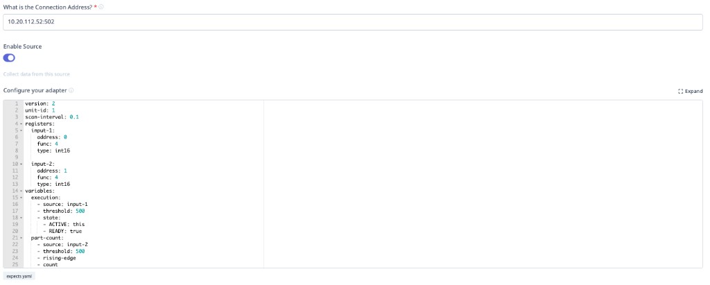
Step 4: Add an adapter script — mandatory before any data appears
The connection address routes network traffic to your I/O module. It does not tell MachineMetrics what the signals mean. You must paste a Transform Adapter Script into the "Configure your adapter" field below the connection address.
Without a script:
- The device may show as reachable
- No utilization, part count, or alarm data will appear
- This is the most common reason I/O integrations appear to fail
See the worked examples below for ready-to-use scripts for Sealevel and WISE modules.
Step 5: Save and verify
Click Save. The machine should connect within 30–60 seconds. Navigate to the machine timeline to confirm signals are being received.
Modbus Data Types
Sealevel eI/O-170:
- Analog Inputs:
int16(0-4095 raw counts) - Digital Inputs: Boolean (coils)
WISE-4050:
- Digital Inputs: Boolean (coils)
Tip: Use Max — MachineMetrics’ AI assistant — to help generate or refine Digital I/O adapter scripts for your wired signals. The examples below are starting points.
Reference Documentation:
Example 1: CT for Execution (Main Spindle)
Hardware: Sealevel eI/O-170E
- AN1: Main spindle CT (analog 0-10V model)
Configuration:
version: 2
unit-id: 1

registers:
  spindle-raw:
    address: 0 # AN1
    func: 4 # Read Input Registers
    type: int16 # Raw ADC counts (0-4095)

variables:
  # Convert raw ADC counts to voltage (0-10V range)
  # 4096 counts = 10V, so divide by 409.6 to get voltage
  ct-voltage-int:
    - source: spindle-raw / 409.6 # Intermediate voltage (0.0 to 10.0 VDC)

  # Create cleaned version for data output (reduces noise/database load)
  ct-voltage:
    - source: ct-voltage-int
    - resample: 0.5 # Sample every 500ms
    - min-delta: 0.1 # Only report changes >0.1V

  # Execution based on voltage threshold with off-delay
  execution:
    - source: ct-voltage-int > 1.15 # 1.15V threshold
    - off-delay: 10 # 10 second off-delay (prevents flicker)
    - state:
        - ACTIVE: this
        - READY: true

data-items:
  - execution
  - ct-voltage # Send cleaned voltage value for trending
Key Points:
- Raw ADC is 0-4095 (12-bit)
- Divide by 409.6 to convert to 0-10V
- Create intermediate variable (
ct-voltage-int) for threshold logic - Create cleaned variable (
ct-voltage) with resample and min-delta for data output - Use cleaned version in
data-itemsto reduce database load - 1.15V threshold catches low-speed operations
- 10-second off-delay prevents flicker during rapid start/stop
Example 2: Multiple CTs (Main Spindle + Live Tooling + Z-Axis)
Hardware: Sealevel eI/O-170E
- AN1: Main spindle CT
- AN2: Live tooling head CT
- AN3: Z-axis drive CT
- Opto 1: Part eject signal (dry contact)
Configuration:
version: 2
unit-id: 1

registers:
  main-spindle-raw:
    address: 0 # AN1
    func: 4
    type: int16

  live-tool-raw:
    address: 1 # AN2
    func: 4
    type: int16

  z-axis-raw:
    address: 2 # AN3
    func: 4
    type: int16

coils:
  part-eject:
    address: 0 # Opto 1
    func: 2 # Read Discrete Inputs

variables:
  # Convert all CTs to voltage (intermediate)
  main-spindle-voltage-int:
    - source: main-spindle-raw / 409.6

  live-tool-voltage-int:
    - source: live-tool-raw / 409.6

  z-axis-voltage-int:
    - source: z-axis-raw / 409.6

  # Create cleaned versions for data output
  main-spindle-voltage:
    - source: main-spindle-voltage-int
    - resample: 0.5
    - min-delta: 0.1

  live-tool-voltage:
    - source: live-tool-voltage-int
    - resample: 0.5
    - min-delta: 0.1

  z-axis-voltage:
    - source: z-axis-voltage-int
    - resample: 0.5
    - min-delta: 0.1

  # Machine active if ANY spindle/axis has current
  execution:
    - source: main-spindle-voltage-int > 1.0 or live-tool-voltage-int > 1.0 or z-axis-voltage-int > 0.8
    - off-delay: 10
    - state:
        - ACTIVE: this
        - READY: true

  # Part count on eject signal
  part-count:
    - source: part-eject
    - rising-edge
    - count

data-items:
  - execution
  - part-count
  - main-spindle-voltage
  - live-tool-voltage
  - z-axis-voltage
Key Points:
- Monitors three different motors/drives
- Uses OR logic: active if any has current
- Lower threshold for Z-axis (0.8V) as it draws less current
- Intermediate variables (
-intsuffix) for threshold logic - Cleaned variables with resample/min-delta for data output
- Separate voltage values for analysis/trending
Example 3: Stack Lights + Dry Contact Part Count
Hardware: WISE-4050
- DI0: Green light (24VDC wet contact)
- DI1: Yellow light (24VDC wet contact)
- DI2: Part count relay (dry contact with external 24VDC)
- DI3: Red light (24VDC wet contact)
Machine Behavior:
- Green ON + Yellow OFF = In cycle (ACTIVE)
- Green ON + Yellow ON = Operator stop (INTERRUPTED)
- Red ON = Alarm (INTERRUPTED)
- All OFF = Idle (READY)
Configuration:
version: 2
unit-id: 1

coils:
  green-light:
    address: 0 # DI0
    func: 2 # Read Discrete Inputs
  yellow-light:
    address: 1 # DI1
    func: 2
  part-relay:
    address: 2 # DI2
    func: 2
  red-light:
    address: 3 # DI3
    func: 2

variables:
  # Complex execution state from light combination
  execution:
    - state:
        - INTERRUPTED: red-light # Alarm
        - INTERRUPTED: green-light and yellow-light # Op-stop
        - ACTIVE: green-light and yellow-light == false # In cycle
        - READY: true # Idle

  # Part counter
  part-count:
    - source: part-relay
    - rising-edge
    - count

data-items:
  - execution
  - part-count
  - green-light
  - yellow-light
  - red-light
Key Points:
- Order matters in
state:(first match wins) - Check alarm and op-stop before checking active
- Use
== falseinstead ofnotfor clarity - Send individual light states for diagnostics
Example 4: Pallet Changer on Mill
Hardware: WISE-4050
- DI0: Pallet index complete signal
- DI1: Auto mode signal
- DI2: Spindle running (from CT with dry contact output)
Configuration:
version: 2
unit-id: 1

coils:
  pallet-index:
    address: 0 # DI0
    func: 2 # Read Discrete Inputs
  auto-mode:
    address: 1 # DI1
    func: 2
  spindle:
    address: 2 # DI2
    func: 2

variables:
  # Active when spindle running
  execution:
    - source: spindle
    - off-delay: 10
    - state:
        - ACTIVE: this
        - READY: true

  # Count parts on pallet change (only in auto mode)
  part-count:
    - source: pallet-index and auto-mode # Both must be true
    - rising-edge
    - count

data-items:
  - execution
  - part-count
  - auto-mode
Key Points:
- Use
andoperator for combination logic - Pallet index only counts in auto mode
- Prevents false counts during manual pallet changes
Example 5: Barfeeder Pulse on Lathe
Hardware: Sealevel eI/O-170E
- AN1: Main spindle CT
- Opto 1: Barfeeder advance complete signal
Configuration:
version: 2
unit-id: 1

registers:
  spindle-raw:
    address: 0 # AN1
    func: 4
    type: int16

coils:
  barfeed-pulse:
    address: 0 # Opto 1
    func: 2 # Read Discrete Inputs

variables:
  # Spindle monitoring (intermediate conversion)
  spindle-voltage-int:
    - source: spindle-raw / 409.6

  # Cleaned version for data output
  spindle-voltage:
    - source: spindle-voltage-int
    - resample: 0.5
    - min-delta: 0.1

  execution:
    - source: spindle-voltage-int > 1.0
    - off-delay: 10
    - state:
        - ACTIVE: this
        - READY: true

  # Count on barfeed advance (new part started)
  part-count:
    - source: barfeed-pulse
    - rising-edge
    - count

data-items:
  - execution
  - part-count
  - spindle-voltage
Key Points:
- Barfeed advance indicates new part cycle starting
- Each bar advance = 1 part (adjust if multiple parts per bar)
- May need to count on part eject instead depending on machine
Example 6: Coolant Pulse Method (Last Resort)
Hardware: Sealevel eI/O-170E
- AN1: Spindle CT
- Opto 1: Coolant pump contactor (dry contact)
⚠️ WARNING: Use this method only when other part counting methods are not available. Requires program modifications and uses 2 pulses.
M-Code in Part Program:
M08          ; Coolant ON (pulse 1)
G04 P0.5     ; Wait 0.5 seconds
M09          ; Coolant OFF
G04 P0.5     ; Wait 0.5 seconds
M08          ; Coolant ON (pulse 2)
G04 P0.5     ; Wait 0.5 seconds
M09          ; Coolant OFF
M30          ; Program end
Configuration:
version: 2
unit-id: 1

registers:
  spindle-raw:
    address: 0 # AN1
    func: 4
    type: int16

coils:
  coolant-raw:
    address: 0 # Opto 1
    func: 2 # Read Discrete Inputs

variables:
  # Spindle monitoring (intermediate conversion)
  spindle-voltage-int:
    - source: spindle-raw / 409.6

  # Cleaned version for data output
  spindle-voltage:
    - source: spindle-voltage-int
    - resample: 0.5
    - min-delta: 0.1

  execution:
    - source: spindle-voltage-int > 1.0
    - off-delay: 10
    - state:
        - ACTIVE: this
        - READY: true

  # Filter coolant signal to verify pulse duration
  coolant-filtered:
    - source: coolant-raw
    - min-delta: 0.4 # Must be on for at least 0.4 seconds
    - max-delta: 0.7 # Must be on for no more than 0.7 seconds

  # Count on filtered coolant signal (2 pulses = 1 part)
  pulse-count:
    - source: coolant-filtered
    - rising-edge
    - count

  # Divide pulse count by 2 to get part count
  part-count:
    - source: pulse-count / 2

data-items:
  - execution
  - part-count
  - spindle-voltage
Key Points:
min-deltaandmax-deltaverify pulse duration (0.4-0.7 sec)- Prevents false counts from normal coolant operation
- Two pulses required per part (divide count by 2)
- Adds wear to coolant pump (use sparingly)
- Requires modification of all part programs
Example 7: Auto Mode Filtering
Hardware: WISE-4050
- DI0: Auto mode signal
- DI1: Part ejector signal
- DI2: Green light
Problem: Part ejector can be triggered manually during setup. Only count parts in auto mode.
Configuration:
version: 2
unit-id: 1

coils:
  auto-mode:
    address: 0 # DI0
    func: 2 # Read Discrete Inputs
  part-ejector:
    address: 1 # DI1
    func: 2
  green-light:
    address: 2 # DI2
    func: 2

variables:
  # Execution from green light
  execution:
    - source: green-light
    - state:
        - ACTIVE: this
        - READY: true

  # Part count ONLY when in auto mode (using AND logic)
  part-count:
    - source: part-ejector and auto-mode # Both must be true
    - rising-edge
    - count

data-items:
  - execution
  - part-count
  - auto-mode
Key Points:
- Use
andoperator to combine conditions - Prevents false counts during manual operation
- Common requirement for automated equipment
Example 8: Injection Molding Machine
Hardware: WISE-4050
- DI0: Mold closed (wet contact)
- DI1: Auto mode (wet contact)
- DI2: Injection in progress
- DI3: Alarm
Configuration:
version: 2
unit-id: 1

coils:
  mold-closed:
    address: 0
    func: 2 # Read Discrete Inputs
  auto-mode:
    address: 1
    func: 2
  injection:
    address: 2
    func: 2
  alarm:
    address: 3
    func: 2

variables:
  # Execution state
  execution:
    - state:
        - INTERRUPTED: alarm
        - ACTIVE: injection and auto-mode
        - READY: true

  # Count parts on mold closing (only in auto)
  part-count:
    - source: mold-closed and auto-mode # Both must be true
    - rising-edge
    - count

data-items:
  - execution
  - part-count
  - auto-mode
  - alarm
Counter Mode Scripts
These go with counter mode on a WISE module, where the pulse is counted in hardware and read as a holding register.
Simple Example: Basic Part Counter (WISE DI0)
This is the minimal working configuration for a WISE device counting parts via a high-frequency counter on DI0. This script uses a fast scan-interval and derives execution state from counter activity.
Hardware Setup:
- WISE-4050 or WISE-4050/LAN
- DI0: Part count pulse signal (configured as counter in WISE web interface)
Configuration:
version: 2
unit-id: 1
scan-interval: 0.25

registers:
  part-count:
    address: 0 # DI0 counter register
    func: 3
    type: uint16

variables:
  counter-changed:
    - source: part-count
    - value-increase

  execution:
    - source: counter-changed
    - off-delay: 10 # hold on the run signal for 10s
    - state:
        - ACTIVE: this
        - READY: true

data-items:
  - execution
  - part-count
Key Points:
address: 0, func: 3reads the DI0 counter register using raw PDU addressingtype: uint16is correct for counters — values are always positive (0–65,535)scan-interval: 0.25polls the counter every 250ms (suitable for high-frequency signals)value-increasedetects when the counter goes up; used to drive execution stateoff-delay: 10keeps the machine in ACTIVE state for 10 seconds after the last pulse
Sample Script: RPM Calculation from Encoder
Hardware Setup:
- WISE-4050 or WISE-4050/LAN
- DI0: Encoder pulse output (configured as counter in WISE web interface)
- Encoder: 60 pulses per revolution (PPR)
- Resample interval: 5 seconds
Configuration:
version: 2
unit-id: 1

registers:
  encoder-count:
    address: 0 # DI0 counter register
    func: 3
    type: uint16

variables:
  # Track count increase (pulses since last reading)
  pulse-diff:
    - source: encoder-count
    - value-increase-diff # Returns difference from last reading
    - resample: 5 # Sample counter every 5 seconds

  # Calculate RPM from pulse difference
  # Formula: RPM = (pulses / PPR) * (60 / resample_interval)
  # With 60 PPR and 5-second resample: RPM = (pulses / 60) * (60 / 5)
  # Simplified: RPM = pulses / 5
  spindle-rpm:
    - source: pulse-diff / 5
    - expression: round(this, 0) # Round to whole number

  # Optional: Execution state from RPM
  execution:
    - source: spindle-rpm > 100 # Active if RPM > 100
    - state:
        - ACTIVE: this
        - READY: true

data-items:
  - spindle-rpm
  - encoder-count
  - execution
Key Points:
address: 0, func: 3reads the DI0 counter using raw PDU addressingtype: uint16is correct for counters (unsigned 0–65,535)resample: 5in the variable pipeline samples the counter value every 5 seconds- More accurate and reliable than using
scan-interval value-increase-diffreturns the count increase since last reading- RPM formula depends on PPR (pulses per revolution) and resample interval
- Roll-over is handled automatically by
value-increase-diff
Note: The
resampleparameter goes in the variables section, not on the register definition.
Sample Script: High-Speed Part Counting
Hardware Setup:
- WISE-4050
- DI1: Part sensor configured as counter in WISE web interface
- Part sensor pulses once per part
- Resample interval: 1 second
Configuration:
version: 2
unit-id: 1

registers:
  parts-counter:
    address: 1 # DI1 counter register
    func: 3
    type: uint16

variables:
  # Extract count difference and accumulate
  part-count:
    - source: parts-counter
    - value-increase-diff # Get new parts since last poll
    - resample: 1 # Sample counter every 1 second
    - count # Accumulate into total

  # Calculate parts per minute (production rate)
  parts-per-minute:
    - source: parts-counter
    - value-increase-diff
    - resample: 1 # Sample counter every 1 second
    - expression: this * 60 # Scale 1-second reading to per-minute

  # Execution based on production activity
  execution:
    - source: parts-per-minute > 5 # Active if producing
    - off-delay: 30 # Hold for 30 seconds
    - state:
        - ACTIVE: this
        - READY: true

data-items:
  - part-count
  - parts-per-minute
  - parts-counter
  - execution
Key Points:
- Counter mode ensures no pulses are missed on fast production lines
address: 1, func: 3reads the DI1 counter using raw PDU addressingtype: uint16is correct for counters (unsigned 0–65,535)resample: 1in the variable pipeline samples the counter value every 1 secondvalue-increase-diffgets new parts since last readingcountoperation accumulates differences into running total- Scale to per-minute by multiplying by
60 / resample_interval - Counter will roll over at 65,535 (handled automatically)
Note: The
resampleparameter goes in the variables section, not on the register definition.
RPM Calculation Reference
General RPM Formula:
RPM = (pulses_per_scan / pulses_per_revolution) * (60 / scan_interval_seconds)
Example Calculations:
| PPR | Scan Interval | Pulses Counted | RPM Calculation |
|---|---|---|---|
| 60 | 5 seconds | 300 | (300/60) * (60/5) = 60 RPM |
| 1 | 5 seconds | 50 | (50/1) * (60/5) = 600 RPM |
| 100 | 1 second | 50 | (50/100) * (60/1) = 30 RPM |
| 360 | 5 seconds | 1800 | (1800/360) * (60/5) = 60 RPM |
Simplified Formulas for Common Configurations:
# 60 PPR, 5-second resample:
pulse-diff:
  - source: encoder-count
  - value-increase-diff
  - resample: 5
spindle-rpm:
  - source: pulse-diff / 5

# 1 PPR (1 pulse per revolution), 5-second resample:
pulse-diff:
  - source: encoder-count
  - value-increase-diff
  - resample: 5
spindle-rpm:
  - source: pulse-diff * 12

# 100 PPR, 1-second resample:
pulse-diff:
  - source: encoder-count
  - value-increase-diff
  - resample: 1
spindle-rpm:
  - source: pulse-diff * 0.6

# 360 PPR, 5-second resample:
pulse-diff:
  - source: encoder-count
  - value-increase-diff
  - resample: 5
spindle-rpm:
  - source: pulse-diff / 30
Complete Working Example: WISE High-Frequency Counter
This is a real-world configuration using a WISE unit with DI0 configured as a counter.
Hardware Setup:
- WISE-4050 or WISE-4050/LAN
- DI0: High-frequency pulse input (configured as counter in WISE web interface)
- DI0 also used for execution state detection
Basic Counter Configuration:
version: 2
unit-id: 1

coils:
  di0:
    address: 0 # Digital input state (still available)
    func: 2 # Read Discrete Inputs

registers:
  counter1:
    address: 0 # DI0 counter register
    func: 3 # Read Holding Registers
    type: uint16

variables:
  execution:
    - source: di0 # Use digital input state
    - resample: 0.1 # Sample every 100ms for fast response
    - state:
        - ACTIVE: this
        - READY: true

data-items:
  - di0 # Current input state
  - execution # Derived state
  - counter1 # Counter value
With RPM Calculation:
version: 2
unit-id: 1

coils:
  di0:
    address: 0
    func: 2

registers:
  counter1:
    address: 0 # DI0 counter register
    func: 3
    type: uint16

variables:
  # Calculate pulses since last reading
  pulse-diff:
    - source: counter1
    - value-increase-diff
    - resample: 5 # Sample counter every 5 seconds

  # Calculate RPM (assuming 60 pulses per revolution)
  # Formula: (pulses / 60 PPR) * (60 seconds / 5 second resample)
  # Simplified: pulses / 5
  spindle-rpm:
    - source: pulse-diff / 5
    - expression: round(this, 0)

  # Execution from RPM threshold
  execution:
    - source: spindle-rpm > 100
    - state:
        - ACTIVE: this
        - READY: true

data-items:
  - di0
  - execution
  - counter1
  - spindle-rpm
Key Points:
address: 0, func: 3reads the DI0 counter using raw PDU addressingtype: uint16is correct — counter values are always positive (0–65,535)- Digital input coil (DI0 state) uses
address: 0, func: 2— same channel, different function code resamplein variables controls sampling frequency for each data point- Both the counter value and input state are output
Note: The
resampleparameter goes in the variables section, not on registers or at the global level.
Counter Roll-Over Handling
Since the counter is uint16, it will roll over at:
- Maximum: 65,535
- Rolls to: 0
The value-increase-diff operation handles this roll-over automatically, so your counts remain accurate even after roll-over occurs.
Troubleshooting Counter Mode
Counter not incrementing:
- Verify input is configured as counter in WISE web interface
- Check signal wiring and voltage (should be 10-50VDC for wet contact)
- Test signal with multimeter or oscilloscope
- Ensure signal frequency is within WISE specifications
Incorrect RPM or count:
- Verify PPR (pulses per revolution) for your encoder
- Check scan interval matches script configuration
- Confirm register address matches DI channel
- Test with known RPM source for calibration
Counter resets unexpectedly:
- Check WISE power supply stability
- Verify network connectivity (dropped connections can cause resets)
- Review WISE system logs in web interface
Related Articles
- Wiring Examples — the diagrams these scripts belong to
- Adapter Script Reference — full syntax for the transform language