Digital I/O Troubleshooting
Cannot Connect to Module
Diagnostic Steps:
- Check Power
- Sealevel: Power LED green?
- WISE: Power LED on?
- Measure voltage at terminals: 24VDC ±10%
- Check Network
- Cable fully seated in RJ45?
- Link lights blinking?
- Try different cable or switch port
- Check IP Address
- Sealevel default: 192.168.42.253
- WISE default: 192.168.1.1 or DHCP
- Is computer on same subnet?
- Ping Module
- Open command prompt
ping 192.168.42.253(or module IP)- Should receive replies
Signal Not Detected
Diagnostic Steps:
- Measure Voltage
- Use multimeter
- Measure between input terminal and common
- Should read signal voltage when active
- Should read near 0V when inactive
- Check Wiring
- Terminals tight?
- Correct polarity?
- Any broken wires?
- Verify Modbus Address
- Sealevel: AI0=register 0, Opto 1=coil 0
- WISE: DI0=coil 0, DI1=coil 1, etc.
- Test with Configuration Tool
- Sealevel: Use MaxSSD utility
- WISE: Use web interface diagnostics
- Confirm signal reaches module
Current Transducer (CT) State Detection Issues
Current transducers measure electrical current to determine machine state (Active/Idle). Use this systematic approach to diagnose and resolve CT-related issues.
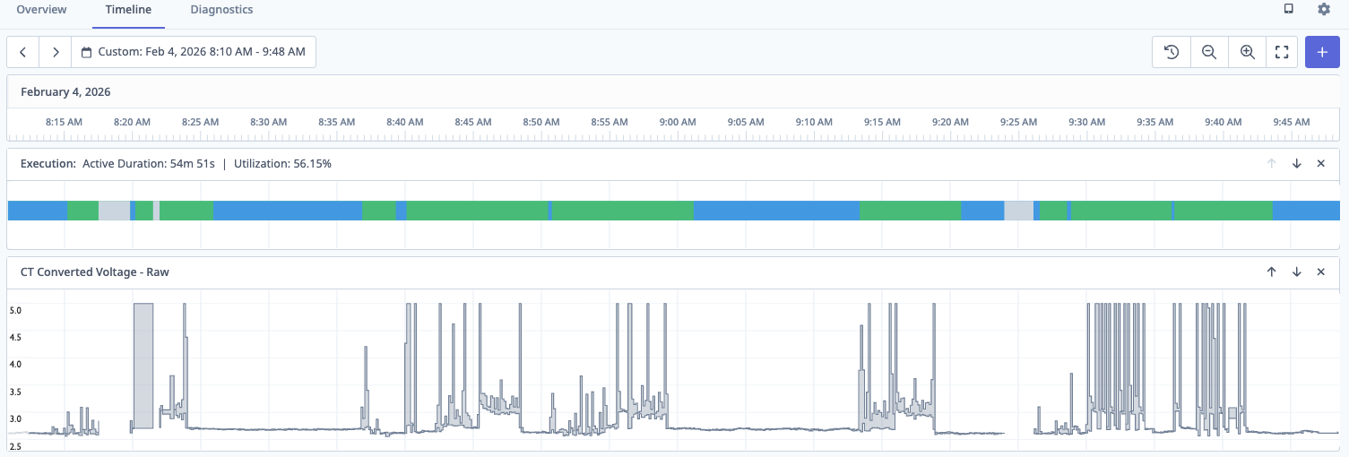
Common Symptoms:
- Machine shows Idle while physically running
- Machine shows Active while physically idle
- Erratic switching between Active and Idle states
- Machine state never changes
⚠️ CRITICAL PRINCIPLE: When a machine is completely idle (spindle off, no motors running), the CT voltage should be very low (typically 0.5V - 1.5V). If you see high voltage during idle, the CT is in the wrong location or measuring the wrong circuit.
Understanding CT Switch Positions
Most analog CTs (0-10V output) have three switch positions that determine the current measurement range:
| Switch Position | Current Range | When to Use |
|---|---|---|
| 1 (Low) | 0-50A | Small motors, low-power equipment |
| 2 (Medium) | 0-100A | Most spindle motors, typical CNC equipment |
| 3 (High) | 0-200A | Large motors, high-power machines |
How to Choose: Check the motor nameplate for rated current, then select the switch position that covers that range. Too low = CT maxes out; too high = poor signal separation.
Diagnostic Steps:
-
Review Current Configuration
- Navigate to Machines → [Machine] → Settings → Data Collection
- Document current threshold value and off-delay setting
-
Observe CT Behavior in Timeline
- Go to Machine → Timeline view and enable Live Mode
- Add "CT Converted Voltage - Raw" data item to timeline
- Watch the signal for several minutes while machine cycles
-
Verify Physical Installation
| Checkpoint | ✅ Correct | ❌ Incorrect |
|---|---|---|
| Clamp closure | Fully closed, no gap | Gap visible between halves |
| Cable type | Single conductor only | Multiple wires or cable bundle |
| Location | Spindle motor or main power | General building power |
| Interference | 18"+ from VFDs/transformers | Adjacent to high-voltage equipment |
- Perform Live Testing (Most Critical Step)
Stand at the machine and observe CT voltage during these states:
Test A: Machine Completely Idle
- Spindle OFF, no motors running
- Record idle voltage range (should be < 2.0V)
- If higher: CT is on wrong circuit or switch position too high
Test B: Spindle Running (Not Cutting)
- Start machine, activate spindle at normal speed
- Record active voltage range
Test C: Production (Cutting)
- Load part and begin cutting operation
- Record cutting voltage range
- Calculate Optimal Threshold
Optimal Threshold = (Max Idle Voltage + Min Active Voltage) / 2
Example:
- Idle range: 0.8V to 1.5V (Max = 1.5V)
- Active range: 3.2V to 5.0V (Min = 3.2V)
- Calculation: (1.5 + 3.2) / 2 = 2.35V
- Set threshold to 2.3V or 2.5V
⚠️ Important: You need at least 0.5V separation between max idle and min active.
- Update Adapter Script Configuration
Navigate to Machines → [Machine] → Settings → Data Collection and update your adapter script:
variables:
  # Intermediate variable for logic (not output)
  ct-voltage-int:
    - source: spindle-raw / 409.6 # SeaLevel conversion

  # Cleaned variable for data output
  ct-voltage:
    - source: ct-voltage-int
    - resample: 0.5 # Sample every 0.5 seconds
    - min-delta: 0.1 # Only send if changed by 0.1V

  # Execution state based on threshold
  execution:
    - source: ct-voltage-int > 2.5 # Your calculated threshold
    - off-delay: 90 # Optional delay in seconds
    - state:
        - ACTIVE: this
        - READY: true

data-items:
  - execution
  - ct-voltage # Output cleaned variable only
⚠️ CRITICAL Variable Naming:
- Always use TWO variables for CT voltage
- Intermediate variable (
ct-voltage-int): Used for threshold logic, never include in data-items - Cleaned variable (
ct-voltage): Usesresampleandmin-deltato reduce noise, safe for data-items - This prevents database overload from noisy analog signals
Common CT Issues & Quick Solutions:
No voltage signal (flat line at 0V)
- Check physical connections at IO module
- Verify Modbus register address in script
- Test with multimeter or swap CT
Constant high voltage (even when machine is off)
- Turn machine off at breaker - CT should drop to ~0V
- If signal persists, CT is on wrong circuit
- Relocate to machine-specific circuit (spindle motor)
- Ensure only single conductor in CT clamp
- Check CT switch position - try higher range setting
Extreme noise / erratic signal
- Move CT 18"+ away from VFDs and transformers
- Reroute CT cable away from high-voltage runs
- Verify cable shielding is intact
Typical Voltage Ranges (Quick Reference):
| Machine State | Typical Voltage | Diagnosis |
|---|---|---|
| Completely Off (breaker off) | 0V - 0.2V | No current flowing |
| Idle / Standby | 0.5V - 1.5V | ✅ Normal baseline |
| ⚠️ High Idle (PROBLEM) | 2.5V - 4.0V | ❌ Wrong circuit or multiple conductors |
| Spindle Running (no load) | 2.5V - 4.0V | Clear increase from idle |
| Cutting / Under Load | 3.5V - 5.0V | Peak activity |
When to Contact Support:
- No voltage signal despite verified connections
- CT signal doesn't correlate with machine behavior
- Overlapping idle/active voltage ranges after relocating CT
- Adapter script changes don't take effect
Include: Machine name, Timeline screenshots showing CT voltage, documented voltage ranges, photos of CT installation, and current adapter script.
False Part Counts
Solutions:
-
Add Auto Mode Logic
part-count:
  - source: part-signal and auto-mode
  - rising-edge
- count -
Add Pulse Duration Verification (for coolant method)
filtered-signal:
  - source: raw-signal
  - min-delta: 0.4
- max-delta: 0.7 -
Use Correct Edge Detection
- Try
rising-edgevsfalling-edge - Depends on signal behavior
- Try
Best Practices
Planning:
- Study machine operation before selecting signals
- Review electrical schematics
- Test signals under various conditions
- Document everything
Current Transducers:
- Use analog 0-10V CTs for Sealevel eI/O-170 analog inputs
- Use dry contact CTs for Sealevel eI/O-170 digital inputs (Opto 1/2)
- Clamp around ONE phase only
- Secure CT to prevent vibration
- Set low threshold (1.0-1.5V) for low-speed detection
Wiring:
- Use 18-22 AWG stranded wire
- Label all wires clearly
- Keep wiring neat and organized
- For Sealevel digital inputs: DO NOT apply external voltage (internally powered)
Electrical Safety:
- Never apply >50VDC to any input
- Use relays for AC voltages
- Verify voltage with multimeter
- Follow lockout/tagout procedures
- Work with qualified electricians
Configuration:
- Start with simple adapter scripts
- Test incrementally
- Use descriptive variable names
- CRITICAL: Never output raw analog values in
data-items- Create intermediate variable for logic (e.g.,
ct-voltage-int) - Create cleaned variable with
resampleandmin-deltafor output - Only output cleaned variables to reduce noise and database load
- Create intermediate variable for logic (e.g.,
- Reference: Adapter Scripts Introduction
- Keep backup of working configurations
Part Counting:
- Prefer dedicated part count relay
- Use pallet changer signal when available
- Use barfeeder pulse when applicable
- Coolant pulse method is last resort only