Advantech WISE Modules
The WISE-4050 family is the module to use for discrete signals — stack lights, relay contacts, M-code outputs — and for part counting faster than about 10Hz, because it counts in hardware rather than by polling. It has no analog inputs; for a current transducer use Sealevel or a WISE-4012.
Power: 10–30VDC · Default IP: 192.168.1.1 · Protocol: Modbus TCP
Hardware
Preferred wireless I/O solution that customers source directly from Advantech or distributors.
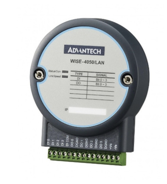
Advantech WISE-4050/LAN Ethernet I/O Module - Wired version with 4 digital inputs. The module features terminal connections for easy wiring and supports Modbus TCP communication. This is the LAN (wired Ethernet) variant; a wireless WiFi version (WISE-4050) is also available.
Specifications
Model: WISE-4050 (Wireless) or WISE-4050/LAN (Wired Ethernet)
Digital Inputs (4 channels):
- Type: Optically isolated
- Voltage Range: 10-50VDC
- Isolation: 3000VDC (optical)
- Wet Contact Compatible: Yes (10-50VDC)
- Dry Contact Compatible: Yes (the module wets the input internally — no external supply)
Wireless Specifications (WISE-4050)
WiFi:
- Standard: IEEE 802.11 b/g/n
- Frequency: 2.4 GHz
- Range: Up to 150m (line of sight)
- Security: WEP, WPA, WPA2-PSK
- Modes: Infrastructure or AP mode
Network Configuration
Default Settings:
- Wireless AP Mode: SSID "WISE-4050-XXXXXX" (last 6 of MAC)
- Default IP: 192.168.1.1 (AP mode) or DHCP (Infrastructure mode)
- Default Login: root / 00000000 (8 zeros)
- Modbus Port: 502
- Web Interface: http://[IP-address]
Sourcing WISE-4050
Purchase Options:
- Direct from Advantech: www.advantech.com
- Distributors: DigiKey, Mouser, Newark, Arrow
- Typical Price: $150-250 USD
Part Numbers:
- WISE-4050: Wireless version
- WISE-4050/LAN: Wired Ethernet version
Additional Items Required for Wireless WISE-4050:
- Antenna extension cable (customer must purchase)
- Type: RP-SMA or compatible with WISE-4050 antenna connector
- Length: 1-3 feet recommended
- Features: Look for cables with magnetic base antenna for easy mounting
- Connects module inside cabinet to antenna outside cabinet
- Installation requirement: Hole must be drilled in electrical cabinet for external antenna mounting
Note: Wireless WISE-4050 requires antenna to be mounted externally to the electrical cabinet for proper WiFi signal reception. See Installation section for details.
Terminal Reference
The WISE-4050 and WISE-4050/LAN are the same module with different radios — identical terminals, switches and Modbus map. The WISE-4012 is a different module with analog universal inputs instead of discrete inputs.
WISE-4050/LAN (wired)
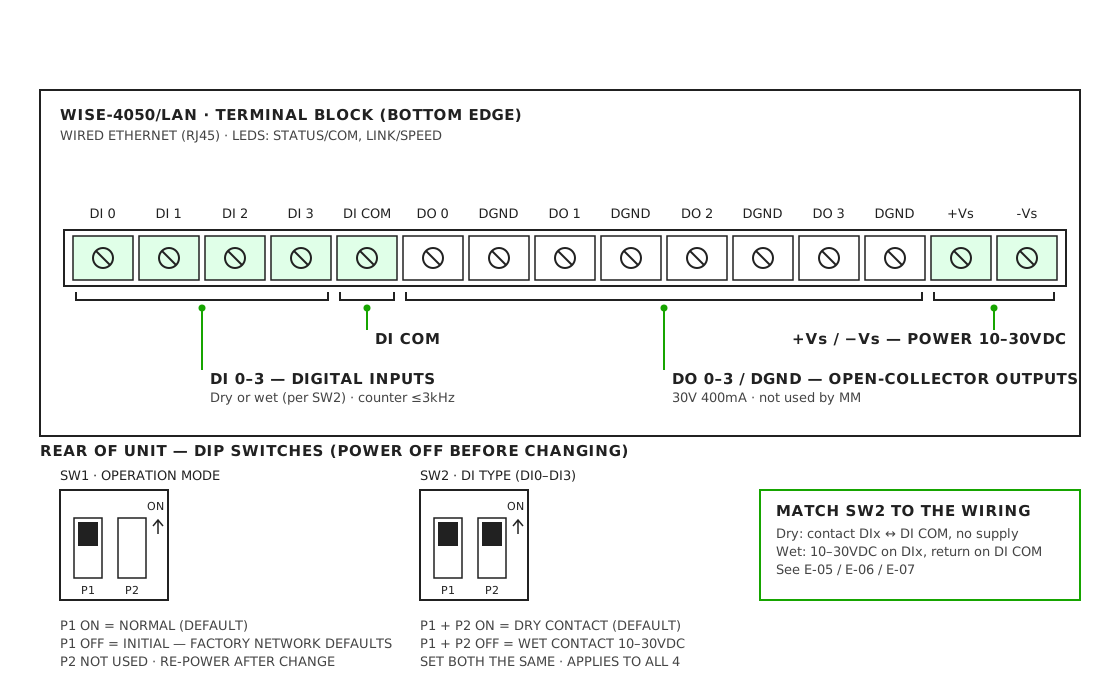
| Terminal | Function | Modbus |
|---|---|---|
| DI 0–3 | Discrete inputs | func: 2 inputs 0–3 · counter: func: 3 holding registers 0–3 |
| DI COM | Common for DI 0–3 | — |
| DO 0–3 | Outputs | Not used by MachineMetrics |
| DGND | Output ground | Not used |
| +Vs / -Vs | Power, 10–30VDC | — |
- Default IP is 192.168.1.1, login
root/00000000. Change the password. - DI COM is shared across all four inputs, so sourcing and sinking signals cannot be mixed on one module.
- SW2 sets all four inputs dry or wet together.
- Power from the MachineMetrics 24VDC supply. Do not use DGND as a power return.
WISE-4050 (wireless)
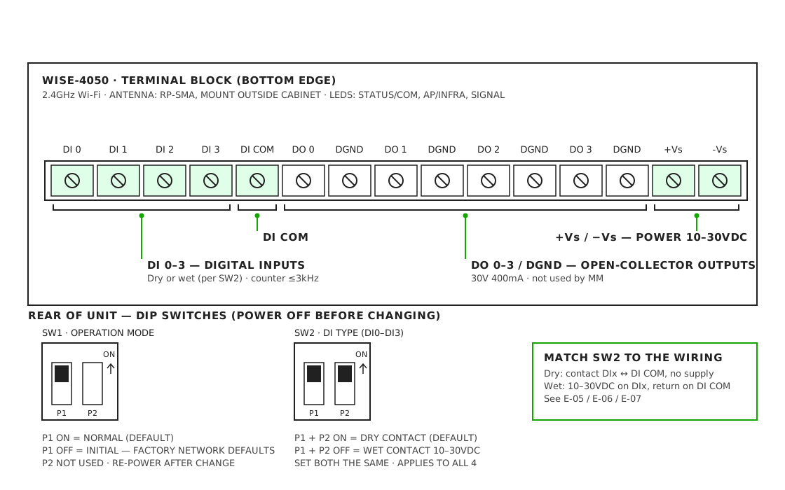
- Boots in AP mode: SSID
WISE-4050-XXXXXXat 192.168.1.1. Switch it to Infrastructure mode to join the shop Wi-Fi. - Drill the cabinet and fit an antenna extension so the antenna sits outside the steel enclosure. A radio inside a closed metal cabinet will not hold a connection.
- SW1 P1 OFF (Initial) restores factory network settings if you lock yourself out.
WISE-4012 (analog universal inputs)

| Terminal | Function |
|---|---|
| V0+ / V0− | Universal input 0 — CT + to V0+, − to V0− |
| V1–V3 ± | Universal inputs 1–3 |
| DO 0–1 | Open-collector outputs — not used |
| D GND | Output ground — not used |
| +Vs / -Vs | Power, 10–30VDC, 2.5W |
- Accepts the standard 0–10V CT directly. Set the channel to 0–10V in the web UI.
- Dry-contact DI mode samples at 2Hz per channel — fine for slow states, useless for part-count pulses. Use a WISE-4050 for counting.
- Current mode needs an external 120Ω resistor across Vn+ / Vn−.
- Confirm the analog register map against the adapter template before relying on it.
Physical Installation
Step 1: Mount Module
- Snap onto 35mm DIN rail
- Mount inside electrical cabinet for protection
Step 2: Antenna Mounting (Wireless WISE-4050 Only)
IMPORTANT: For wireless WISE-4050 modules, the antenna must be mounted externally to the electrical cabinet for proper WiFi signal reception.
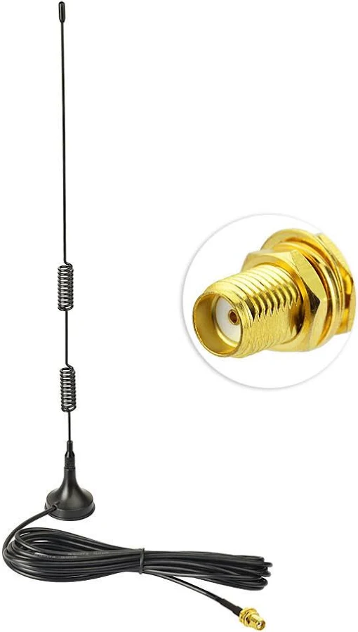
WiFi antenna extension cable with RP-SMA connector - Required for wireless WISE-4050 installations. The extension cable connects the WISE-4050 module inside the electrical cabinet to the antenna mounted outside the cabinet. The cable features spring-coiled sections for flexibility and a magnetic base antenna for easy external mounting.
Antenna Installation Requirements:
-
Drill Hole in Cabinet
- A hole must be drilled in the electrical cabinet wall
- Size: Appropriate for antenna connector/cable (typically 1/2" to 3/4")
- Location: Choose a location with clear line-of-sight to WiFi access points
- Coordinate with machine owner/electrician before drilling
-
Antenna Extension Cable Required
- Customer must purchase an antenna extension cable
- Cable connects WISE-4050 module (inside cabinet) to antenna (outside cabinet)
- Cable type: RP-SMA or compatible with WISE-4050 antenna connector
- Recommended length: 1-3 feet (minimize signal loss)
- Features: Magnetic base antenna for easy mounting
-
Mount Antenna Externally
- Route extension cable through drilled hole
- Attach antenna to outside of cabinet (magnetic base works well on metal cabinets)
- Secure antenna in position with appropriate mounting hardware
- Ensure antenna has clear path for WiFi signals
Note: The WISE-4050/LAN (wired Ethernet version) does not require antenna mounting. Simply connect an Ethernet cable to the module's RJ45 port.
Step 3: Power Connection
24VDC (+) → V+ terminal
24VDC (-) → V- terminal
DIP Switch Configuration
Before wiring signals to the WISE-4050, you must configure the DIP switches on the back of the module to set the input type (wet contact or dry contact) for each digital input channel.
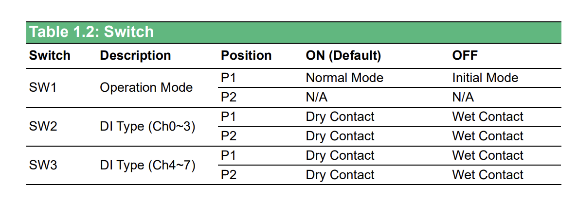
WISE-4050 DIP Switch Configuration - The module has three switches (SW1, SW2, SW3) on the back that control operation mode and input types. On the WISE-4050, SW2 configures all four inputs, DI0 to DI3. Set to ON for dry contact or OFF for wet contact.
DIP Switch Functions:
| Switch | Description | Position | ON (Default) | OFF |
|---|---|---|---|---|
| SW1 | Operation Mode | P1 | Normal Mode | Initial Mode |
| P2 | N/A | N/A | ||
| SW2 | DI Type (Ch0-3) | P1 | Dry Contact | Wet Contact |
| P2 | Dry Contact | Wet Contact |
The WISE-4050 has four inputs, DI0 to DI3, and SW2 sets the type for all four at once. You cannot run some inputs wet and others dry on the same module. SW3 is present on the board but has no channels to configure on a 4-input model.
Understanding Contact Types:
Wet Contact (SW2 OFF)
- The machine provides the voltage on the signal wire — typically 24VDC when active
- Common for stack lights, PLC outputs and relay outputs that carry power
- Wiring: signal to DIx, and DI COM to the source's 0V (sourcing) or +24V (sinking)
- See Wet Contact (24VDC) Inputs
Dry Contact (SW2 ON — default)
- The machine provides a contact closure only, with no voltage on it
- The module wets the input internally, so no external supply is used
- Common for relay contacts, limit switches and mechanical contacts
- Wiring: the contact goes between DIx and the shared DI COM
- See Dry Contact Inputs
Mixed signals: because SW2 is all-or-nothing, convert the minority signal type with interposing relays rather than trying to split the module. See Relays for AC and Mixed Signals.
Important Notes:
⚠️ POWER OFF the WISE-4050 before changing DIP switch settings. Changing switches while powered can damage the module.
⚠️ MATCH SIGNAL TYPE to switch setting. Applying 24VDC to an input configured for dry contact can damage the module.
Once the switches are set, wire the machine signals to match — see Wiring Patterns below.
WiFi Configuration (Wireless Model)
Initial Setup - Connect to WISE AP:
- Power on WISE-4050
- Module creates its own WiFi network on first boot
- SSID:
WISE-4050-XXXXXX(last 6 digits of MAC address) - No password required initially
- Connect Computer to WISE WiFi
- Use laptop or tablet
- Connect to WISE-4050-XXXXXX WiFi network
- Computer will receive IP via DHCP
- Access Web Interface
- Open web browser
- Navigate to:
http://192.168.1.1 - Login:
root - Password:
00000000(8 zeros)
If unsuccessful, check the IP address printed on the back of the device.
Configure for Your Shop WiFi (Infrastructure Mode):
- Change to Infrastructure Mode
- In web interface, go to: Network → WLAN → Mode
- Select: Infrastructure
- Click Submit
- Select Your WiFi Network
- Go to: Network → WLAN → Infrastructure Settings
- SSID: Enter your shop WiFi network name
- Security: Select security type (WPA2-PSK recommended)
- Password: Enter your WiFi password
- Click Submit
- Configure Static IP (Recommended)
- Go to: Network → LAN → Ethernet/WLAN IP Configuration
- Uncheck Enable DHCP
- IP Address: Enter static IP (from IT team)
- Example: 192.168.1.150
- Subnet Mask: 255.255.255.0
- Gateway: Your network gateway
- Click Submit
- Set Modbus Unit ID
- Go to: I/O Status → Modbus Address
- Unit ID: Set to
1(or as required) - Click Submit
- Reboot Module
- Go to: Maintenance → System → Reboot
- Click Reboot
- Module will restart and connect to your WiFi
- Verify Connection
- Reconnect computer to your shop WiFi
- Navigate to new IP address:
http://192.168.1.150(your configured IP) - Should see WISE web interface
- Verify WiFi signal strength in web interface
Important Security Settings:
- Change Default Password
- Go to: Maintenance → Account
- Change password from default
00000000 - Use strong password
- Document password for future access
WISE-4050/LAN Configuration (Wired Model)
- Connect ethernet cable to RJ45 port
- Access web interface at default IP:
http://192.168.1.1 - Login: root / 00000000
- Configure static IP as described above
- Set Modbus Unit ID to 1
Wiring Patterns
Which pattern you use depends on whether the signals carry voltage, and SW2 forces that choice on all four inputs at once. Set the DIP switches before you wire anything — see DIP Switch Configuration. Each pattern below includes the adapter script that reads it.
The schematics on this page are reference wiring, drawn from the manufacturer datasheets. They are not a wiring diagram for your machine. Verify every connection against the machine's own electrical prints before you install, and confirm terminal labels and the Modbus map against the unit in front of you — they vary by firmware revision.
Wet Contact (24VDC) Inputs

- Set SW2 to OFF (wet) with the module powered down. SW2 sets all four channels at once.
- Logic 1 is 10–30VDC at 3mA or more. Logic 0 is 0–3VDC. Anything between 3V and 10V is undefined.
- DI COM is shared by DI0–DI3. For sourcing (PNP) outputs, tie DI COM to the source 0V. For sinking (NPN) outputs, tie DI COM to +24V.
- Inputs are optically isolated from module power, so DI COM returns to the signal source, not to module ground.
- Tap at the output terminal in parallel with the existing load. Do not break the existing circuit.
- AC, above 30VDC, or below 10VDC all need an interposing relay — see Relays for AC and Mixed Signals.
Adapter script
version: 2
unit-id: 1

coils:
  cycle-start:
    address: 0 # DI0 -> discrete input 0
    func: 2
  alarm-signal:
    address: 1 # DI1 -> discrete input 1
    func: 2

variables:
  execution:
    - source: cycle-start
    - off-delay: 10
    - state:
        - ACTIVE: this
        - READY: true

  alarm:
    - source: alarm-signal

data-items:
  - execution
  - alarm

conditions:
  system:
    message: Machine is in fault state
    value:
      FAULT: alarm
Dry Contact Inputs

- SW2 ON (dry) is the factory default. The module wets the input internally, so a contact closed to DI COM reads 1.
- No external supply in dry mode. Applying 24V to an input set for dry contact can damage the module.
- All contacts return to the shared DI COM.
- Three-wire NPN sensors: power them from +24V, tie the sensor 0V to DI COM, and run the output to DIx.
- Counter mode is set per input in the web UI and handles up to 3kHz. Use solid-state outputs for fast pulses — mechanical relays bounce and add about 10ms.
- Counter values read as
func: 3holding registers, where DIx is register x.
Adapter script
This example runs DI0 as a plain dry contact for execution and DI3 in counter mode for part count, which is the usual split.
version: 2
unit-id: 1
scan-interval: 0.25

coils:
  in-cycle:
    address: 0 # DI0 -> discrete input 0
    func: 2

registers:
  part-count:
    address: 3 # DI3 in counter mode -> holding register 3
    func: 3
    type: uint16

variables:
  execution:
    - source: in-cycle
    - off-delay: 10
    - state:
        - ACTIVE: this
        - READY: true

data-items:
  - execution
  - part-count
Relays for AC and Mixed Signals

- WISE wet inputs are DC only. 24VAC and 120VAC signals always need a relay.
- SW2 sets all four channels to one mode, so when signals are mixed you convert the minority type with relays. The plate shows AC and 24VDC relayed to dry contacts so all four inputs can run in dry mode.
- If most signals are 24VDC instead, set SW2 OFF and feed the dry contacts from +24V through the contact to DIx, with DI COM to 0V.
- AC coils need RC or varistor suppression. DC coils need a flyback diode, cathode to +.
- Confirm the added coil current stays within the PLC or CNC output rating.
Adapter script
Relayed signals arrive as dry contacts, so the script is identical to Dry Contact Inputs — the mode is a hardware decision, not a script one.
version: 2
unit-id: 1

coils:
  green-light:
    address: 0 # CR1 N.O. (120VAC stack light) -> DI0
    func: 2
  red-light:
    address: 1 # CR2 N.O. (120VAC stack light) -> DI1
    func: 2
  part-pulse:
    address: 2 # CR3 N.O. (24VDC M-code output) -> DI2
    func: 2

variables:
  execution:
    - state:
        - INTERRUPTED: red-light
        - ACTIVE: green-light
        - READY: true

  part-count:
    - source: part-pulse
    - rising-edge
    - count

  alarm:
    - source: red-light

data-items:
  - execution
  - part-count
  - alarm

conditions:
  system:
    message: Machine is in fault state
    value:
      FAULT: alarm
Counter Mode
For applications requiring RPM tracking or high-frequency pulse counting (e.g., conveyor speed, encoder pulses, production counters), we recommend using a WISE unit (either wireless or wired) configured in counter mode.
When to Use Counter Mode
Common use cases:
- RPM monitoring: Spindle speed from encoder pulses
- Conveyor speed: Tracking belt or chain speed from proximity sensors
- High-speed part counting: Fast production lines with high pulse rates
- Encoder tracking: Position or speed from rotary encoders
- Frequency measurement: Any signal above 10 Hz
Why WISE for High-Frequency?
- Standard digital inputs sample too slowly for fast pulses
- Counter mode accumulates pulses in hardware (no missed counts)
- Can handle frequencies up to several kHz
- Polling adapter reads total count, not individual pulses
Configuring WISE Input as Counter
Step 1: Access WISE Web Interface
- Navigate to WISE IP address in browser:
http://192.168.1.150(your configured IP) - Login:
root/ your password - Go to: I/O Status → Digital Input Configuration
Step 2: Set Input Mode to Counter
- Select the input channel (DI0, DI1, DI2, or DI3)
- Mode: Change from "Digital Input" to "Counter"
- Counter Type: Select "Frequency Counter" or "Pulse Counter"
- Click Submit and Reboot the module
Note: Once an input is set to counter mode, it accumulates pulses continuously. The adapter script reads the current count value and calculates the difference since the last reading.
How Counter Mode Works
Normal Digital Input Mode:
- Adapter reads:
trueorfalse(on/off state) - High-speed pulses may be missed between reads
- Limited to ~10 Hz sampling frequency
Counter Mode:
- Adapter reads: Current accumulated count (integer)
- WISE hardware counts every pulse (no missed counts)
- Adapter calculates:
count_difference = current_count - previous_count - Supports frequencies up to several kHz
Polling Frequency:
- Use
resampleparameter in variables for precise sampling control - For RPM:
resample: 5(5-second sampling) is usually sufficient - For real-time counting: Use
resample: 0.5orresample: 1(500ms or 1-second sampling) - More accurate and reliable than global
scan-interval
Recommended: Place
resamplein the variable pipeline (e.g., aftervalue-increase-diff) for best results.
WISE Counter Register Addresses
When using counter mode, WISE modules expose counter values as Modbus holding registers. Use raw PDU addressing with an explicit func: 3:
| Digital Input | Address (PDU) | Function Code | Type |
|---|---|---|---|
| DI0 | 0 | 3 (Read Holding Registers) | uint16 |
| DI1 | 1 | 3 | uint16 |
| DI2 | 2 | 3 | uint16 |
| DI3 | 3 | 3 | uint16 |
Important: Counter mode changes the input from a boolean coil to a 16-bit register. The digital input coil remains available separately for reading the current state.
address: 0 and not address: 40001?Modbus has two ways to refer to the same register:
| Style | Example | How it works |
|---|---|---|
| 5-digit convention | address: 40001 | The leading 4 implies FC3; remaining digits minus 1 = PDU register |
| Raw PDU addressing | address: 0, func: 3 | Direct 0-based register number; function code declared explicitly |
Both address: 40001 and address: 0, func: 3 point to the exact same physical holding register. For WISE counter registers, raw PDU addressing is required — the DI0 counter lives at PDU register 0 (not 40019). Trying address: 40019 points to PDU register 18, which is a completely different register.
When you use a raw address like 0, the script cannot infer the function code from the number alone, so you must explicitly include func: 3.
Modbus Address Map
Digital Inputs:
- DI0 → Coil 0 (function 2 - Read Discrete Inputs)
- DI1 → Coil 1 (function 2 - Read Discrete Inputs)
- DI2 → Coil 2 (function 2 - Read Discrete Inputs)
- DI3 → Coil 3 (function 2 - Read Discrete Inputs)
Related Articles
- Adapter Scripts — worked scripts, including counter-mode and RPM examples
- Sealevel — the alternative module, required for analog current transducers
- Troubleshooting — connection and signal problems