Sealevel eI/O-170E
The Sealevel eI/O-170E is the module to use when utilization comes from motor current, because it is the only one with analog inputs. It has 8 analog inputs and 2 dry-contact opto inputs.
Power: 9–30VDC on the side terminal, or PoE on the eI/O-170PoE · Default IP: 192.168.42.253 · Protocol: Modbus TCP
Hardware
MachineMetrics' exclusive I/O solution for all new installations. We sell and support only this model.
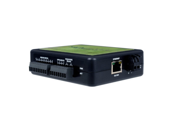
Sealevel eI/O-170 Ethernet I/O Module - A compact DIN-rail mounted device with digital inputs and outputs for connecting to machine signals. This module communicates via Modbus TCP and is commonly used for monitoring machine utilization through current transducers and capturing part counts from machine signals.
Specifications
Analog Inputs (8 channels):
- Voltage Ranges: 0-5V, 0-10V, ±5V, ±10V (software configurable)
- Resolution: 12-bit (4096 counts, 0.00244V per count at 10V range)
- Input Impedance: 100kΩ
- Channels: 8 single-ended OR 4 differential
- Typical Use: Current transducers (analog 0-10V CT models)
Digital Inputs (2 channels - Opto 1 & Opto 2):
- Type: Dry contact sensing (internally powered)
- Isolation: 1000VDC optical isolation
- Source Current: 12mA max
- Wiring: Connect switch/contact between input and common terminal
- ⚠️ CRITICAL: These inputs SOURCE current. DO NOT apply external voltage.
Power Options
Standard Model (eI/O-170E):
- Power: 9-30VDC, 3W typical
- Screw terminals on side of unit
- Use 24VDC shop power
Power over Ethernet (eI/O-170PoE):
- IEEE 802.3af-2003 PoE (Class 0)
- No separate power supply needed
- Single cable for power and data
- Requires PoE switch or injector
Physical Specifications
- Size: 4.5" L × 3.5" W × 1.3" H
- Mounting: DIN rail clip included (35mm rail)
- Terminals: 3.5mm removable screw terminals
- Status LEDs:
- Power (Green): Lights when powered
- Act (Green): Blinks during Modbus TCP activity
- Operating Temp: -40°C to 70°C
Purchasing
- Order from: shop.machinemetrics.com
- MachineMetrics provides pre-configured units
- Full technical support included
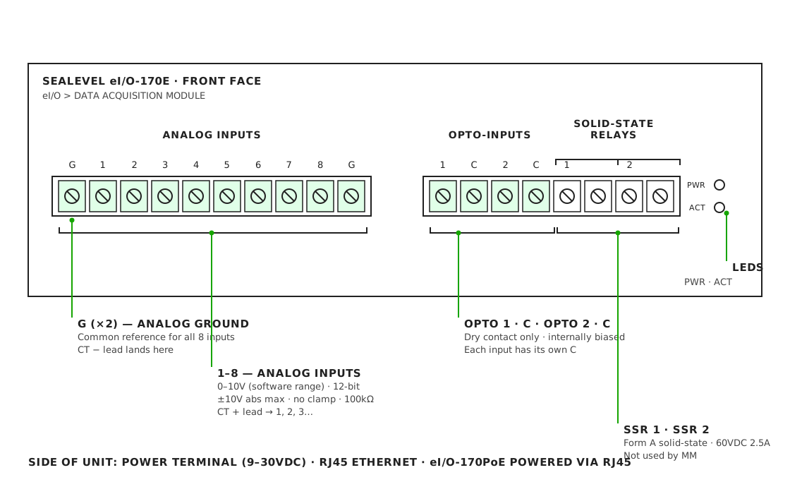
Terminal Reference
| Terminal | Function | Modbus |
|---|---|---|
| Analog 1–8 | Analog in | func: 4 input registers 0–7, int16, 0–4095 counts |
| Analog G | Analog ground (both G are common) | — |
| Opto 1 / C | Dry contact in | func: 2 discrete input 0 |
| Opto 2 / C | Dry contact in | func: 2 discrete input 1 |
| SSR 1, SSR 2 | Solid-state outputs | Not used by MachineMetrics |
| PWR / ACT | Power on / Modbus activity | — |
- Default IP is 192.168.42.253. Change it with SeaMAX Ethernet Config.
- Analog inputs can pair as four differential channels (1–2, 3–4, 5–6, 7–8). MachineMetrics wiring is single-ended to G.
- Each Opto input has its own C. Opto and C are internally biased — never apply external voltage to them.
- Power: side terminal, 9–30VDC on the eI/O-170E, or 802.3af PoE on the eI/O-170PoE.
Physical Installation
Step 1: Mount Module
- Install on 35mm DIN rail in electrical cabinet
- Keep away from high-voltage lines (>240VAC)
- Accessible location for wiring
- Protected from coolant and chips
Step 2: Power Connection
Standard Model (eI/O-170E):
24VDC (+) → V+ terminal (side of module)
24VDC (-) → V- terminal
PoE Model (eI/O-170PoE):
- Connect CAT5/CAT6 ethernet cable
- PoE provides power automatically via ethernet
Step 3: Network Connection
- Connect ethernet cable to RJ45 port
- Connect to network switch
- Module communicates with Edge device over network
Network Configuration
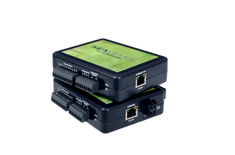
Sealevel I/O Module with terminal connections - The module features multiple digital input and output terminals for wiring machine signals. Note the clear terminal labeling and the RJ45 Ethernet port for network connectivity. This view shows the actual connection points where you'll wire current transducers, part count signals, and other machine I/O.
Step 1: Download SeaMAX Software
- Visit: https://www.sealevel.com/software-seamax-windows
- Download SeaMAX Suite for Windows
- Install as administrator
Step 2: Discover Module
- Launch "Ethernet Config" utility (Start → All Programs → Sealevel Systems → SeaMAX → Ethernet Configuration Tool)
- Click "Search for SeaI/O Devices"
- Modules on network will appear
- Default IP: 192.168.42.253
Step 3: Configure Static IP
- Select module in device list
- Enter new static IP address (from your IT team)
- Example: 192.168.1.101
- Enter subnet mask: 255.255.255.0
- Enter gateway (if required)
- Click "Apply Changes"
- Module will reboot with new IP
Step 4: Verify Connection
- Ping module from Edge device or computer
- Launch MaxSSD utility (Start → All Programs → Sealevel Systems → SeaMAX → MaxSSD Configuration Utility)
- Select "Ethernet" from COM Port dropdown
- Select module IP from list
- Click "Get SeaIO Module Settings"
- Module information should display
Wiring Patterns
Three patterns cover almost every Sealevel install. Each one includes the adapter script that reads it.
The schematics on this page are reference wiring, drawn from the manufacturer datasheets. They are not a wiring diagram for your machine. Verify every connection against the machine's own electrical prints before you install, and confirm terminal labels and the Modbus map against the unit in front of you — they vary by firmware revision.
Analog Current Transducer to the Analog Inputs

- Clamp the CT around one phase conductor between the drive and the motor. Never around the full cable or more than one conductor.
- Orient the CT arrow toward the load.
- Range switch (20 / 40 / 60A): choose the lowest range above the motor's normal running
current. Output is
10V × amps ÷ range, so at 10A the 20A range reads 5.0V, the 40A range 2.5V and the 60A range 1.7V. If the output pins at 10V while cutting, step up a range. For motors above 60A use an SC-651-R2 (50/100/150A) or an SC-651-200. - Configure the channel for 0–10V single-ended. Analog inputs have no overvoltage clamp — never land a 24V signal on one.
- Run 2-conductor shielded twisted pair, 18–22 AWG. Land the drain at Analog G only. Route away from motor leads and the VFD output.
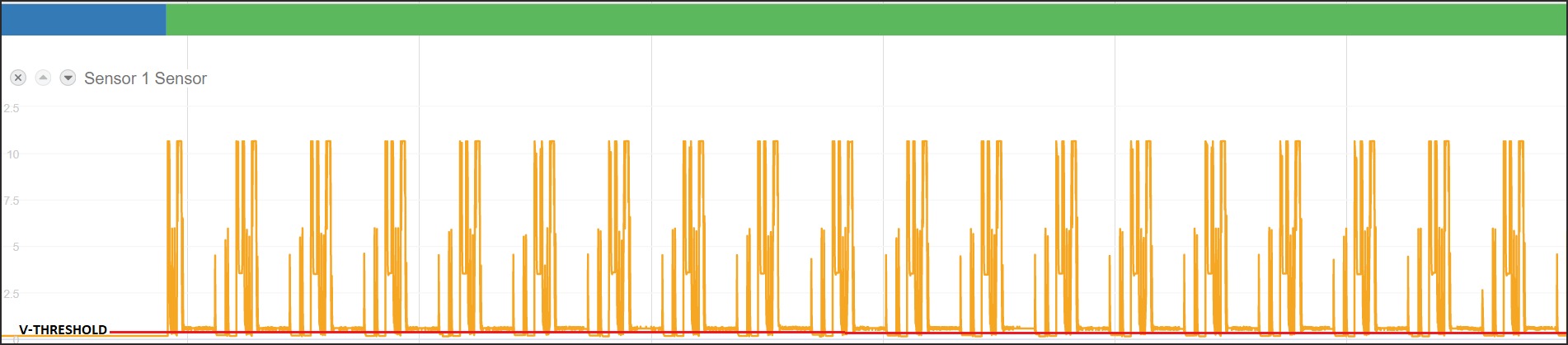
- Scaling: 4096 counts = 10V, so divide counts by 409.6. Idle should read under 1.5V, and a typical ACTIVE threshold is 1.0–1.5V.
- The SC-651 is average-responding and rated for 50/60Hz. On a VFD output the reading is approximate — good enough for run/idle, not for power measurement.
Adapter script
version: 2
unit-id: 1

registers:
  spindle-raw:
    address: 0 # Analog 1 -> input register 0
    func: 4 # Read Input Registers
    type: int16 # Raw ADC counts (0-4095)

variables:
  # 4096 counts = 10V, so counts / 409.6 gives volts.
  ct-voltage-int:
    - source: spindle-raw / 409.6

  ct-voltage:
    - source: ct-voltage-int
    - resample: 0.5
    - min-delta: 0.1

  execution:
    - source: ct-voltage-int > 1.15
    - off-delay: 10
    - state:
        - ACTIVE: this
        - READY: true

data-items:
  - execution
  - ct-voltage
Dry Contacts to the Opto Inputs

- Opto 1 and Opto 2 are dry-contact inputs, each with its own C terminal. The module supplies the sensing current, about 12mA through 330Ω. Opto n shorted to its C reads 1.
- The source must be voltage-free and isolated: spare N.O. relay contacts, limit switches, or a CT switch output.
- Never apply external voltage to Opto or C. A voltage signal such as a 24V stack light has to drive an interposing relay coil first — see Interposing Relays.
- Use contacts rated for low-level switching (gold-flashed or bifurcated). Power contacts may not pass 12mA reliably.
- Solid-state CT switch outputs can be polarity-sensitive. Confirm S1/S2 orientation against the CT datasheet.
- Two discrete inputs only. If you need more, use a WISE-4050.
Adapter script
version: 2
unit-id: 1

coils:
  in-cycle:
    address: 0 # Opto 1 -> discrete input 0
    func: 2 # Read Discrete Inputs
  part-pulse:
    address: 1 # Opto 2 -> discrete input 1
    func: 2

variables:
  execution:
    - source: in-cycle
    - off-delay: 10
    - state:
        - ACTIVE: this
        - READY: true

  part-count:
    - source: part-pulse
    - rising-edge
    - count

data-items:
  - execution
  - part-count
Interposing Relays for Voltage Signals

- Any signal that carries voltage needs a relay on Sealevel — 24VDC (PNP or NPN), 24VAC or 120VAC. The Opto inputs accept contacts only.
- Match the coil voltage to the circuit, and wire the coil in parallel with the existing load so it follows the output exactly.
- DC coils need a flyback diode, cathode to +. AC coils need RC or varistor suppression. Interface relays with built-in suppression satisfy both.
- Use a low-level (gold) N.O. contact, wired Opto n → its own C.
- Confirm the added coil current stays within the PLC or CNC output rating.
- Piggyback option: parallel a coil across A1/A2 of a contactor that already marks the event — a coolant pump, or a spare M-code relay.
Adapter script
The relay contact lands on an Opto input, so the script reads it as a dry contact. Only the hardware differs from Dry Contacts.
version: 2
unit-id: 1

coils:
  green-light:
    address: 0 # CR1 N.O. -> Opto 1 (120VAC lamp circuit)
    func: 2
  m-code-pulse:
    address: 1 # CR2 N.O. -> Opto 2 (24VDC PNP output)
    func: 2

variables:
  execution:
    - source: green-light
    - off-delay: 10
    - state:
        - ACTIVE: this
        - READY: true

  part-count:
    - source: m-code-pulse
    - rising-edge
    - count

data-items:
  - execution
  - part-count
Understanding Current Transducers
Types of Current Transducers
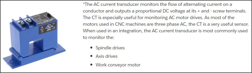
There are two types of CTs for different applications:
1. Analog Output CT (0-10VDC)
For use with Sealevel eI/O-170 Analog Inputs
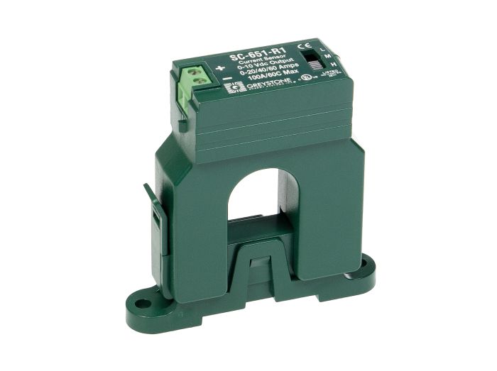
The MachineMetrics standard is the Greystone SC-651-R1.
- Input: 0–20 / 40 / 60A AC, selected with the L / M / H switch on the unit
- Output: 0–10VDC, proportional to current
- Scaling:
10V × amps ÷ range— at 10A the 20A range reads 5.0V, the 40A range 2.5V and the 60A range 1.7V - Self-powered: No external supply needed
- Response: Average-responding, rated 50/60Hz. On a VFD output the reading is approximate — good enough for run/idle, not for power measurement
For motors drawing more than 60A, use an SC-651-R2 (50/100/150A) or an SC-651-200. Other 0–10V clamp CTs work the same way — NK Technologies AT Series, CR Magnetics CR5410, Veris H Series — but check the range, because a fixed-range CT cannot be tuned to the motor the way the SC-651 can.
Wiring to eI/O-170:
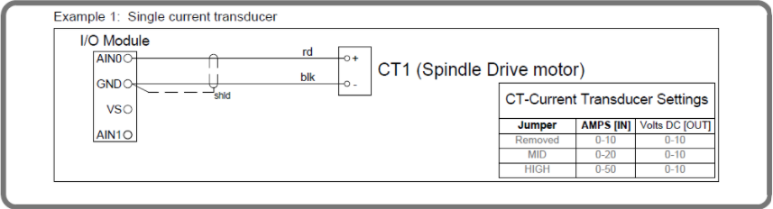
The CT + output goes to an analog input and − to Analog G. See
Analog Current Transducer to the Analog Inputs
for the diagram, the range-selection rule and the adapter script.
Use Cases:
- Spindle motor monitoring (main utilization signal)
- Live tooling head monitoring
- Axis drive monitoring (Z-axis, etc.)
- Any motor-driven activity detection
2. Dry Contact Output CT (Switch Closure)
For use with Sealevel eI/O-170 Digital Inputs (Opto 1 & Opto 2)
Specifications:
- Input: 0-100A AC (adjustable setpoint)
- Output: Dry contact closure when current exceeds setpoint
- Requires: Nothing external — the Opto input supplies its own sensing current
- Adjustable Trip Point: Set threshold for switch activation
Common Models:
- NK Technologies AS2 Series
- Veris H800 Series with switch output
Wiring to eI/O-170 Digital Input:
The switch output is a dry contact, so it wires straight between Opto 1 and its own C — exactly like any other contact. See Dry Contacts to the Opto Inputs for the diagram and the adapter script.
⚠️ Do not add an external supply. The Opto input sources its own 12mA. Solid-state switch outputs can be polarity-sensitive, so confirm S1/S2 orientation against the CT datasheet.
Use Cases:
- Simple on/off detection (machine running or not)
- When analog resolution not needed
- Cost-effective solution
Installing a Current Transducer
Step 1: Identify Motor to Monitor
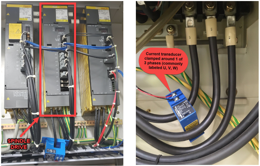
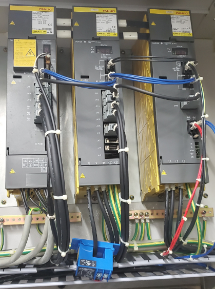
- Usually spindle motor drive
- Could be live tooling head
- Could be axis drive (Z-axis for lathes)
- For multi-spindle: CT on each spindle
Step 2: Access Motor Power Wires
- Open electrical cabinet
- Find motor drive or contactor
- Identify three phase wires (L1, L2, L3)
Step 3: Install CT
- Clamp CT around ONE phase wire only (any of the three)
- Arrow on CT should point toward motor
- Secure CT so it doesn't vibrate loose
- Do not clamp around multiple wires
- Do not clamp around insulated cable bundle (individual wire only)
Step 4: Wire CT Output
- Analog CT: Connect to Analog 1 and Analog G — see Analog Current Transducer to the Analog Inputs
- Dry Contact CT: Connect between Opto 1 and its C, with no external supply — see Dry Contacts to the Opto Inputs
What good CT data looks like in MachineMetrics:
Modbus Address Map
Analog Inputs:
- AN1 → Register 0 (function 4, type int16)
- AN2 → Register 1 (function 4, type int16)
- AN3 → Register 2 (function 4, type int16)
- AN4 → Register 3 (function 4, type int16)
- AN5 → Register 4 (function 4, type int16)
- AN6 → Register 5 (function 4, type int16)
- AN7 → Register 6 (function 4, type int16)
- AN8 → Register 7 (function 4, type int16)
Digital Inputs (Opto 1 & Opto 2):
- Opto 1 → Coil 0 (function 2 - Read Discrete Inputs)
- Opto 2 → Coil 1 (function 2 - Read Discrete Inputs)
Related Articles
- Adapter Scripts — worked scripts for every pattern above
- WISE — the alternative module, for more discrete inputs or fast counting
- Troubleshooting — connection and signal problems