Brother D Series
D Series (D00) controls connect over OPC-UA, which is the recommended method for this series. Enable the OPC-UA server on the control, set a static IP, then point MachineMetrics at it.
Protocol: OPC-UA · Port: 4840 · Endpoint: opc.tcp://<machine_ip>:4840 · Cable: the standard network port on the control
For where the cable goes physically, see Physical Connection in the OPC-UA overview.
IP addresses are entered without dots, with each octet padded to three digits — 172.22.3.34 becomes 172022003034. Getting this wrong is the most common cause of a
Brother connection failing to come up.
The Brother Adapter in FTP mode also supports D00 when configured with
cnc-version: d00. Use it only when OPC-UA cannot be enabled — it collects less data and
needs FTP credentials.
Control Setup
Step 1: Access Communication Menu
- From main screen, press DATABANK soft key
- Select 7. Communication parameter
- Navigate to Ethernet/FTP settings
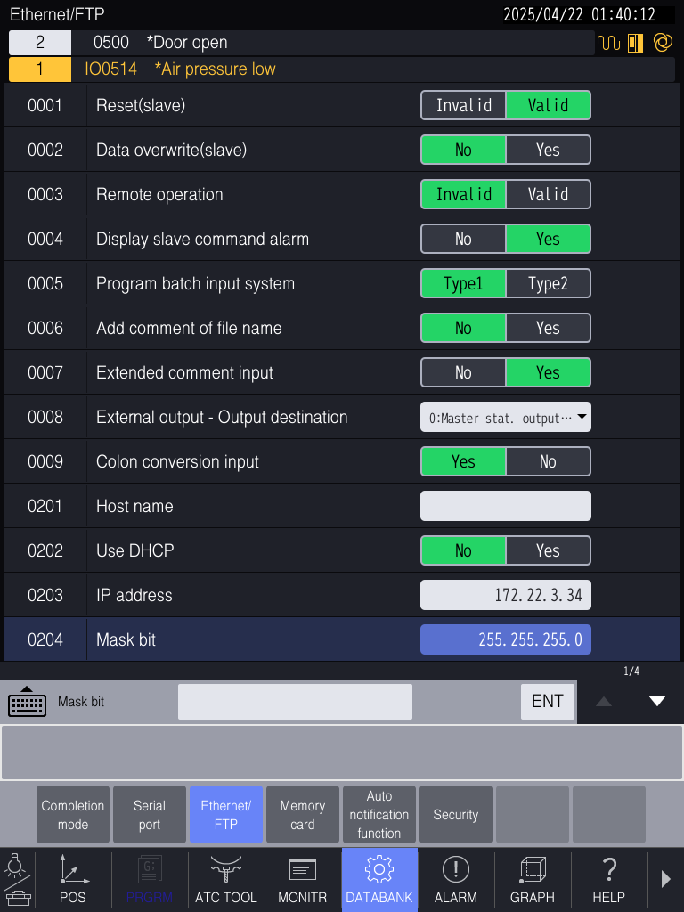
Step 2: Configure Static IP
- 0202 - Use DHCP → Set to
No - 0203 - IP address → Enter the IP as a 12-digit number, padding each octet to three
digits and omitting the dots:
172.22.3.34→17202200303410.1.50.200→010001050200
- 0204 - Mask bit → Typically
255.255.255.0
Step 3: Configure Network Access
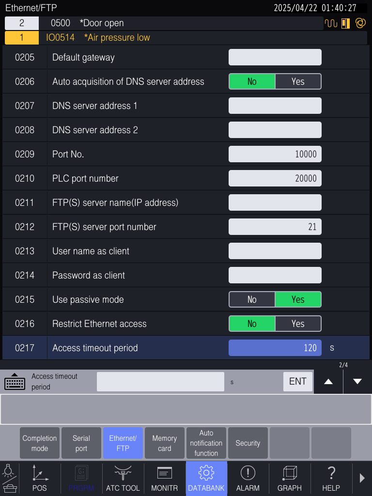
- 0004 - Display slave command alarm → Set to
No - 0216 - Restrict Ethernet access → Set to
No
Step 4: Enable OPC-UA
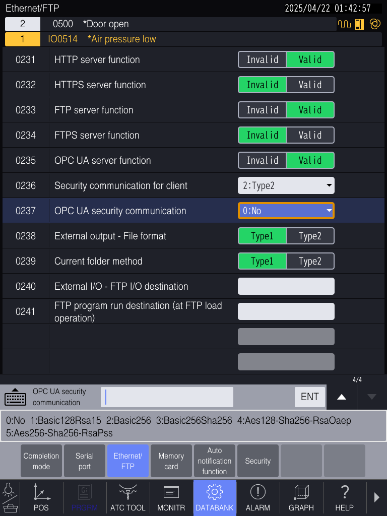
Navigate to final Ethernet/FTP menu screen:
- 0235 - OPC UA server function → Set to
Valid - 0236 - Security communication for client → Set to
2: Type2 - 0237 - OPC UA security communication → Set security level:
0: No- No username/password (simplest)1-5- RSA/AES encryption with authentication
Step 5: Save Settings
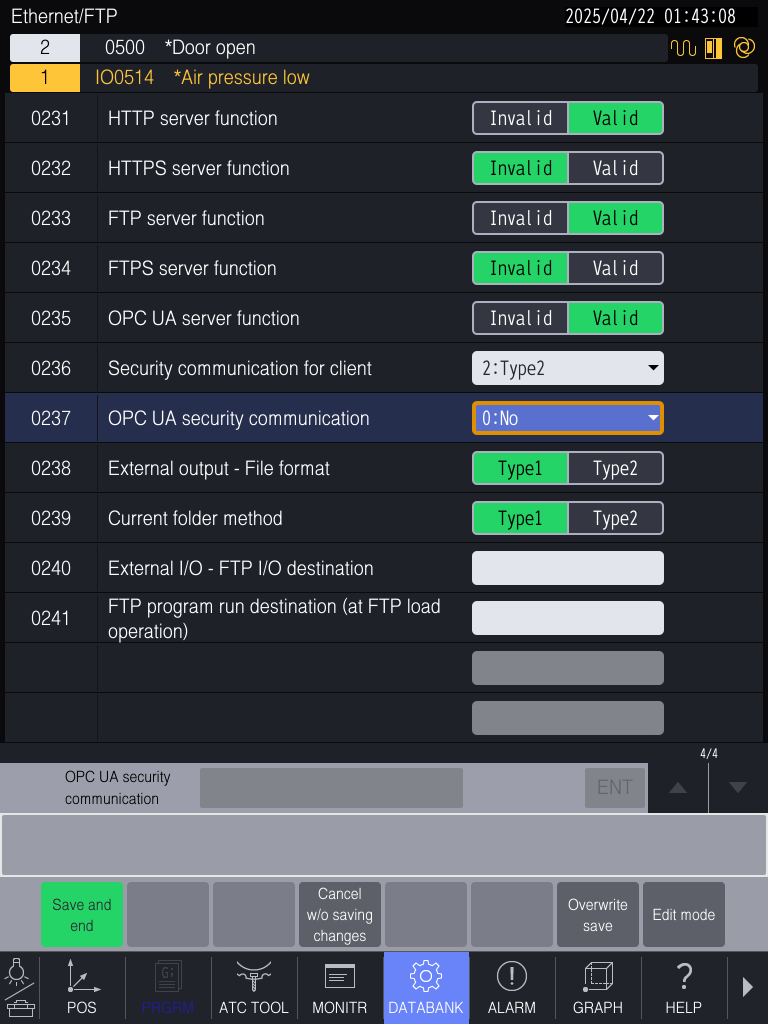
- Press Save and end (bottom left)
- Or use Overwrite save to continue editing
⚠️ Critical: If you don't save, all changes are lost on shutdown/reboot.
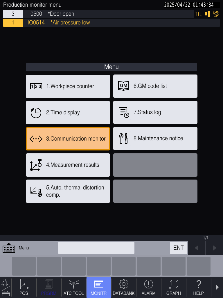
Step 6: Verify Connectivity
- Press MONITR soft key
- Select 3. Communication monitor
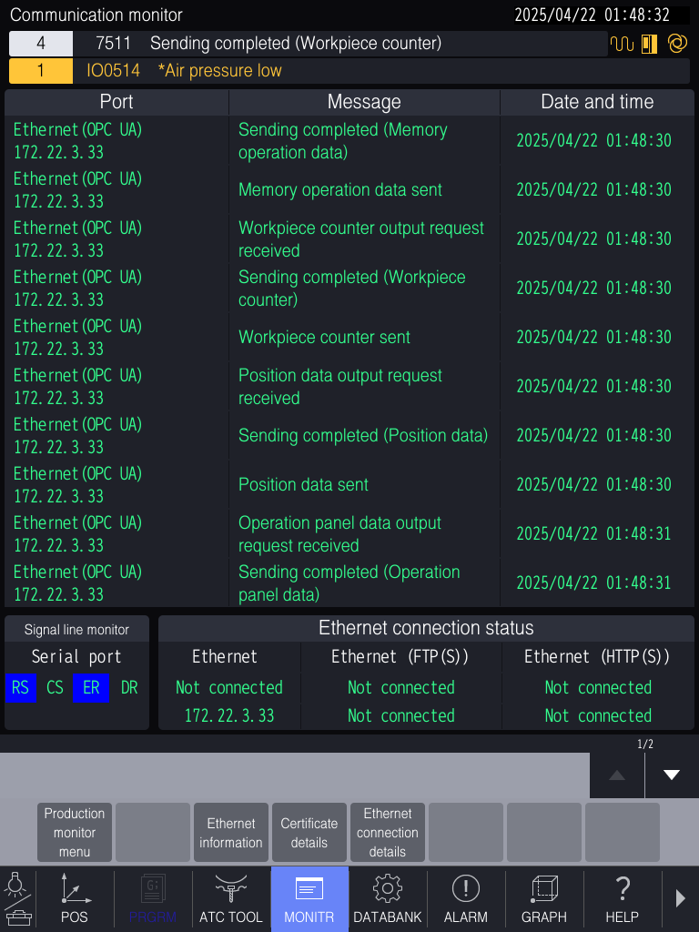
- Look for
Ethernet (OPC UA)in Port column - Message column should show:
Sending completedData sentOutput request received
Step 7: Check Ethernet Information
- In MONITR menu, select Ethernet information
- Verify displays:
- IP Address (as configured)
- Subnet Mask
- Gateway
- MAC Address
- DHCP status
MachineMetrics Setup
With the OPC-UA server running on the control, add the machine's endpoint in MachineMetrics.
-
Go to Assets → Machines and open the machine.
-
On the Data Collection tab, add an OPC-UA data collection method and select the Edge device that will connect to this machine.
-
Enter the connection string, using the IP you set on the control — in normal dot notation here, not the control's 12-digit format:
opc.tcp://[ip-address]:4840For example:
opc.tcp://10.103.112.62:4840 -
Set the security policy to match 0236 — Security communication for client on the control. Type2 is the usual value.
-
Test the connection, then save.

Sample Adapter Script
Paste this into the adapter script field on the data collection method. It is a working starting point for a D00 control — it reads four nodes and derives execution state, program identity, part count, feedrate override and controller mode from them.
version: 2
type: opc-ua
read-mode: polling

tags:
  MEM:
    path: ns=3;s=NC/MemoryOperation/MEM
  wkcntr:
    path: ns=3;s=NC/ProductionMonitor/WKCNTR
  PDSP:
    path: ns=3;s=NC/System/PDSP
  mode:
    path: ns=3;s=NC/System/Mode
variables:
  execution:
    - source: MEM
    - pattern-match:
        pattern: /^(?:[^,]*,){3}\s*([^,]+)/
        group: 1
    - state:
      - ACTIVE: this == 1
      - READY: true
  program-name:
    - source: MEM
    - pattern-match:
        pattern: /^(?:[^,]*,){1}\s*'([^']+)'/
        group: 1
  program-number:
    - source: MEM
    - pattern-match:
        pattern: /^(?:[^,]*,){2}\s*'([^']+)'/
        group: 1
  part-counter:
    - source: wkcntr
    - pattern-match:
        pattern: /^(?:[^,]*,){2}\s*([^,]+)/
        group: 1
  nc-mode:
    - source: mode
  feed-ovr:
    - source: PDSP
    - pattern-match:
        pattern: /^(?:[^,]*,){115}\s*([^,]+)/
        group: 1
  program:
    - source: program-name
data-items:
  - execution
  - program-name
  - program-number
  - part-counter
  - feed-ovr
  - nc-mode
  - program
How the script works
Brother's D00 OPC-UA server does not expose one node per value. Instead, each of the nodes
above returns a single comma-separated string containing many fields, so the script reads
the node once and then uses
pattern-match to pull individual fields out
of it by position.
The regular expressions all follow the same shape. /^(?:[^,]*,){3}\s*([^,]+)/ means "skip
three comma-separated fields, then capture the next one" — so changing the number in {3}
changes which field you read. That is why feed-ovr uses {115}: the feedrate override sits
at that offset in the PDSP string.
| Node | What it carries | Fields used |
|---|---|---|
NC/MemoryOperation/MEM | Memory operation status | Running state, program name, program number |
NC/ProductionMonitor/WKCNTR | Workpiece counters | Part count |
NC/System/PDSP | Position and display data | Feedrate override |
NC/System/Mode | Controller mode | Used directly, no parsing needed |
A few notes on adapting it:
read-mode: pollingis deliberate. The adapter subscribes to value changes by default, but polling is the reliable choice on these controls. See Read Options to tunescan-intervalalongside it.- Verify the field offsets on your machine. The positions above were observed on a particular control and firmware. If a value reads back wrong or empty, browse the node, look at the raw comma-separated string, and count the fields to find the correct offset.
executionis intentionally coarse — it reportsACTIVEwhile the program runs andREADYotherwise. Add further states to thestateblock if your process needs them.- Namespace index
ns=3is typical for this server, but confirm it when browsing. See Browsing OPC-UA Servers if the paths don't resolve.
After saving, map the resulting data items (particularly part-counter) to the correct
MachineMetrics data types under Machine Settings → Data Mapping.
Setting Up the Part Counter
The sample script's part-counter reads the control's workpiece counter, so it only moves if
the counter on the control increments once per finished cycle. D00 controls have four
workpiece counters; these steps use counter 1.
Set the counter values on the control
- Press MONITR and open Workpiece counter.
- For counter 1, set the current value to the parts already made in this run (or
0for a new run). - Optionally set the target (shown as completion) to the run quantity, for the operator's reference on the control.
Make the program increment the counter
The counter does not count on its own. A program arms it with an M-code, and the control adds to it when the program ends:
M211arms counter 1 (M212–M214arm counters 2–4).- When the program reaches
M02orM30, each armed counter goes up by its count value (#3801for counter 1). - Arming is cleared by
M02/M30, the RESET key, power-on, orM221–M224, so the M-code has to run in every program cycle. A cycle that is reset part-way through is not counted.
Add these two lines just before the program end:
O1000 (WORKPIECE COUNTER EXAMPLE)
...
(MACHINING)
...
#3801=1 (PARTS PRODUCED PER CYCLE)
M211 (ARM WORKPIECE COUNTER 1)
M30 (COUNTER 1 INCREMENTS HERE)
If a cycle produces more than one part, such as a fixture holding four parts, set #3801 to
that number so each program end adds the right amount.
Rather than editing programs by hand, add the #3801 and M211 lines to your CAM post
processor's program-end section so every program you post counts the same way. If your post
supports user-defined properties, expose the parts-per-cycle value as a property so
programmers can set it per job.
Workpiece counter variables
Each counter's values can be read and written from a program as macro variables:
| Counter | Count (added per cycle) | Current value | Target (completion) | Arm / cancel |
|---|---|---|---|---|
| 1 | #3801 | #3802 | #3803 | M211 / M221 |
| 2 | #3811 | #3812 | #3813 | M212 / M222 |
| 3 | #3821 | #3822 | #3823 | M213 / M223 |
| 4 | #3831 | #3832 | #3833 | M214 / M224 |
Check the count in MachineMetrics
Run a cycle and compare part-counter in MachineMetrics with counter 1's current value on the
control. If they differ, browse the NC/ProductionMonitor/WKCNTR node, find the field that
matches counter 1's current value, and adjust the offset in the part-counter pattern (see
How the script works).
Related Articles
- Brother Connectivity — all Brother series and connection methods
- Troubleshooting — connection and data problems
- OPC-UA Connectivity Guide — how the protocol works and how to browse a server