Brother C Series
C Series (C00) controls connect with the Brother Adapter, which reads the control's built-in web interface and FTP server over Ethernet. Decide which collection mode you want first — see How the Brother Adapter Collects Data — then work through the control, then MachineMetrics.
Cable: the NIC port in the machine's main electrical cabinet · IP format: 12 digits, no dots (10.172.83.1 is entered as 010172083001)
Earlier C00 firmware may not report properly — in particular, part count is unavailable over HTTP on older page formats. Use FTP mode or a workpiece counter instead.
Prerequisites
Before beginning setup, ensure you have:
Hardware:
- Brother CNC machine with C00 or D00 control
- MachineMetrics Edge device configured on your network
- Network cable (Cat5e or Cat6)
Network:
- Available IP address for the machine
- Network connectivity between machine and Edge device
- Firewall rules configured (see Network Requirements Guide)
Access:
- Physical access to machine control panel
- Access to machine's Data Bank menu
- Administrator/maintenance password (if required)
MachineMetrics:
- Machine added to MachineMetrics (see Adding Machines Guide)
- Edge device installed and connected
Control Setup
The screenshots below show a C00 control. On D00 controls the equivalent settings (IP address, FTP server credentials, Restrict Ethernet access) are found in the same Ethernet/FTP communication parameter screens; see D Series for D00 screenshots of these screens.
Step 1: Confirm Ethernet/FTP Tab Exists
Access Communication Parameters:
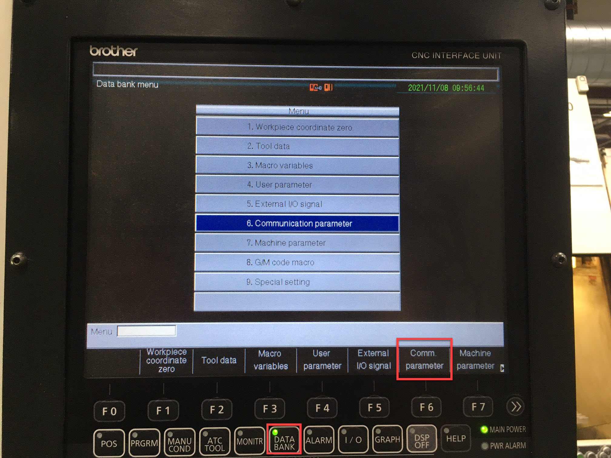
- Press the DATA BANK hardkey on the control panel
-
Press the Communication Parameter softkey (F6)
-
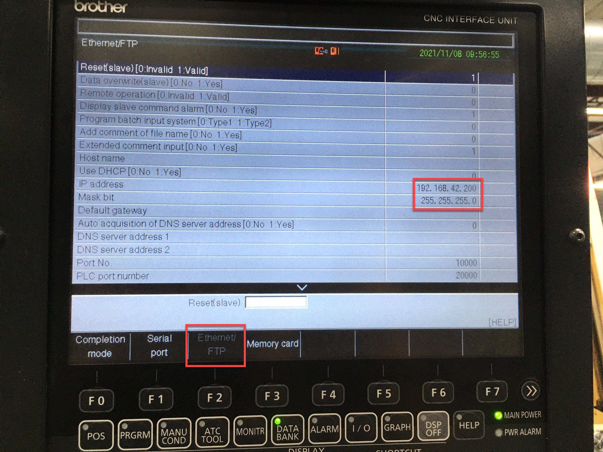
Confirm you see the Ethernet/FTP tab
Note: If you don't see the Ethernet/FTP tab, your control may not support network connectivity. Contact Brother or MachineMetrics support.
Step 2: Set IP Address on Machine
Navigate to the Ethernet/FTP tab and configure the network settings.
Configure IP Address:
- Select IP address field
- Enter your static IP address
- Configure Mask bit (subnet mask)
- Configure Default gateway (if required)
Important: Make sure the Edge device can communicate with whatever IP range you configure. Coordinate with your IT team for proper network settings.
IP Address Entry Format:
Depending on your control type, you may need to enter the IP address in a specific format:
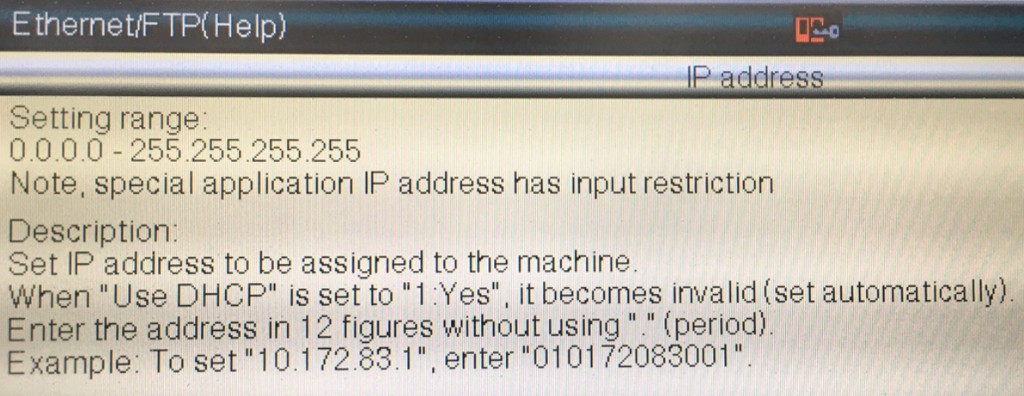
Format: Enter the address in 12 figures without using "." (period).
Example: To set 10.172.83.1, enter 010172083001
Step 3: Disable "Display Slave Command Alarm"
The "Display slave command alarm" option must be set to 0 (off).
How to configure:
- In the Ethernet/FTP settings, scroll down to find Display slave command alarm
- Set the value to 0 (No/Off)
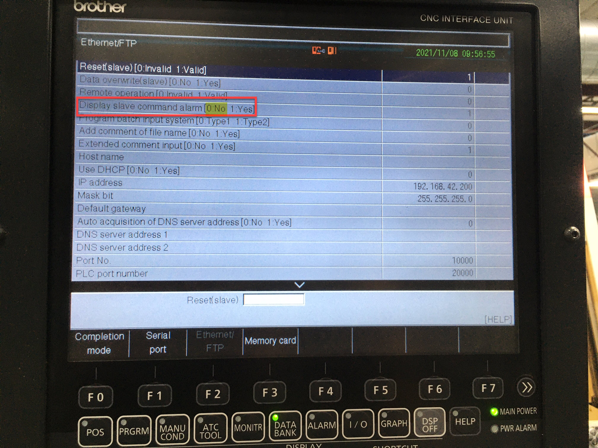
Why: This prevents the machine from displaying error alarms when MachineMetrics queries data from the control.
Step 4: Disable "Restrict Ethernet Access" (Firmware 12+)
On machines with firmware version 12 or newer, "Restrict Ethernet Access" must be set to 0 (off).
How to configure:
- In the Ethernet/FTP settings, find Restrict Ethernet access
- Set the value to 0 (No/Off)
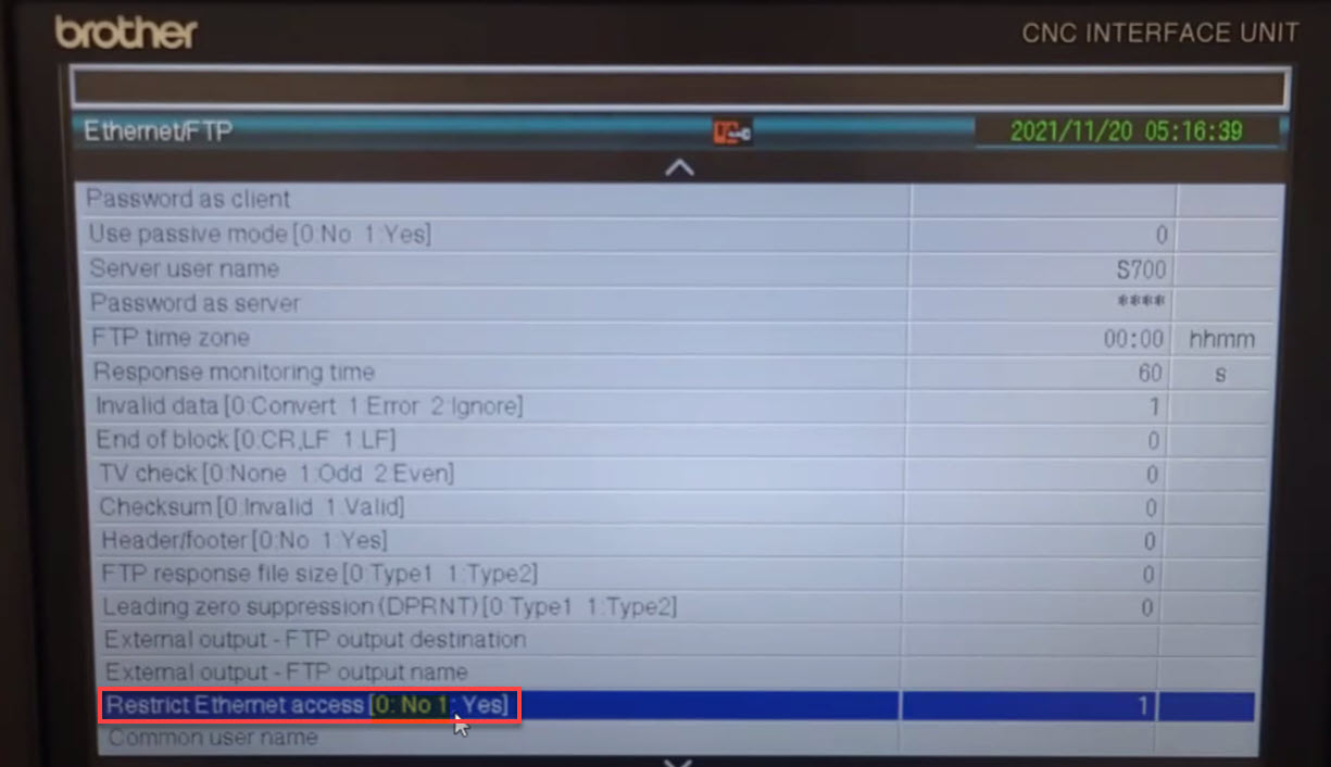
Note: This setting only appears on newer firmware versions. If you don't see this option, your firmware is older than version 12.
Step 5: Configure FTP Server Credentials (Mixed Mode and FTP Mode Only)
If you're using Mixed Mode (recommended for C00) or FTP Mode (including all D00 installations), you need to configure the machine's FTP server username and password.
Skip this step if you're using HTTP Mode only.
Server credentials, not client credentials
The Ethernet/FTP page lists two separate pairs of credentials, and only one of them is the one you want. The control can act as an FTP client (reaching out to someone else's server) or as an FTP server (accepting incoming connections). MachineMetrics connects to the control, so the control is the server:
| Field on the control | Set it? | Why |
|---|---|---|
| Server user name | ✅ Yes | The username the adapter logs in with |
| Password as server | ✅ Yes | The password the adapter logs in with |
| User name as client | ❌ Leave blank | Only used when the control connects out to another FTP server. Not used by MachineMetrics |
| Password as client | ❌ Leave blank | Same — not used by MachineMetrics |
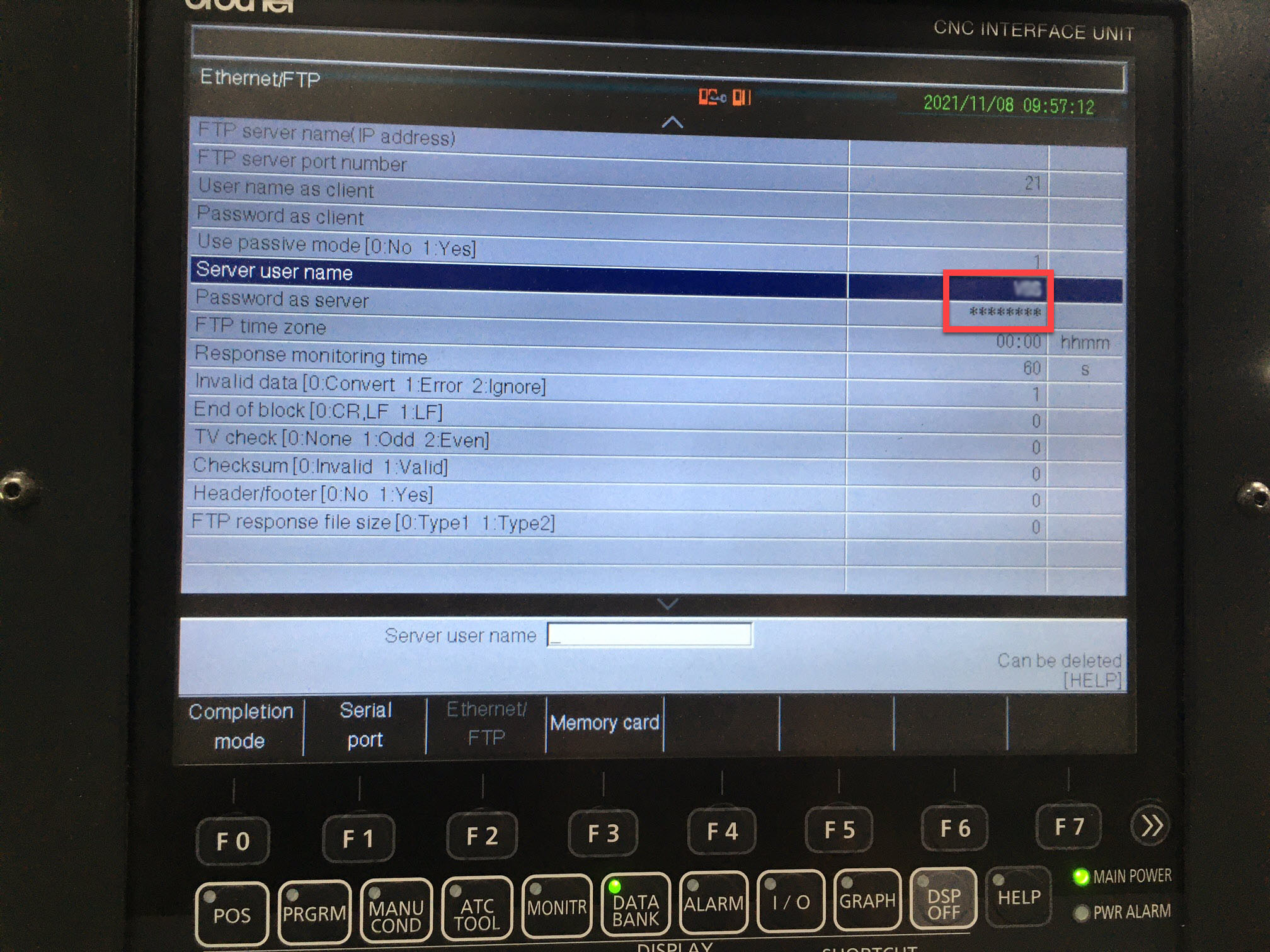
The client fields sit directly above the server fields on the same screen, so it's easy to fill in the wrong pair. If the client fields are set and the server fields are left blank, the adapter has nothing to authenticate against and the connection fails. Leave the client fields empty.
How to configure:
- In the Ethernet/FTP settings, select Server user name and enter a username
- Select Password as server and enter a password
- Confirm User name as client and Password as client are both empty
Keep these values short and simple. The control's input fields are limited, and the adapter
has to reproduce them exactly — a short alphanumeric value such as BRO1 avoids trouble. Some
machines arrive with a server username already set (S700 is common); you can reuse it as long
as you know the matching password.
Whatever you enter here has to be typed identically into the username and password keys of
the adapter script in MachineMetrics Setup.
They are case-sensitive, and a trailing space on either side will cause an authentication
failure. Record them before you leave the machine.
Step 6: Save Changes
To save all changes:
- Press F0 (Completion Mode)
- Select Cancel W/Save Changes
- Control will save the configuration
Important: Changes may require a control restart to take effect. Follow your machine's procedures for restarting the control.
Step 7: Connect Machine to Network
Physical Connection:
Plug the ethernet cable into the NIC port in the machine's main electrical cabinet:
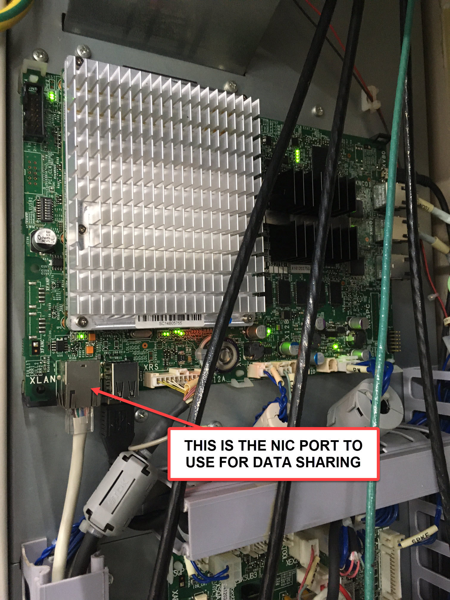
Verify Connection:
- Check link lights on the ethernet port (should be lit/blinking)
- From a computer on the same network, ping the machine's IP address:
ping 192.168.42.200
(Replace with your machine's IP address)
- Verify successful ping responses
MachineMetrics Setup
Once the control is configured and reachable on the network, add the Brother data collection method to the machine in MachineMetrics.
Step 1: Navigate to the Machine's Edit Page
- Log into MachineMetrics
- Go to Assets → Machines
- Find your Brother machine in the list
- Click on the machine to open its page
- Click the Edit icon or Data Collection tab
Step 2: Add the Brother Data Collection Method
- Click Add Data Collection Method
- Select Brother HTTP adapter
- Select the Edge device to connect to this machine
Step 3: Configure the Brother Data Collection Method
Select Edge Device:
- Choose the Edge device that will connect to this machine
Connection Address:
- Enter the machine's IP address configured in Step 2
- Format:
<IP address> - Example:
192.168.42.200
Adapter Script Configuration:
Configure the adapter script based on your desired connection mode.
username and password must match the controlIn Mixed and FTP mode these two keys are the Server user name and Password as server you set in Control Setup step 5. They are not credentials you invent here, and they are not the control's "as client" fields. If they don't match the control character for character, the connection fails to authenticate.
Example: Mixed Mode (Recommended for C00)
This is a complete working script. Replace BRO1 in both places with the credentials you set
on the control:
version: 2
collection-mode: mixed
username: BRO1
password: BRO1
scan-interval: 5
http-interval: 0.1
The scan-interval and http-interval values here poll the control more gently than the
adapter defaults (1.0 and 0.05), which keeps the C00's web interface responsive while still
updating often enough for monitoring. Use these as your starting point and only tighten them if
you need faster updates.
Example: FTP Mode (C00)
version: 2
collection-mode: ftp
username: BRO1
password: BRO1
Example: FTP Mode (D00)
version: 2
collection-mode: ftp
cnc-version: d00
username: BRO1
password: BRO1
Example: HTTP Mode
HTTP mode does not authenticate, so it takes no credentials — leave the control's FTP fields alone entirely:
version: 2
collection-mode: http
Parameters:
| Parameter | Default | Required | Description |
|---|---|---|---|
version | — | ✅ | Adapter script format version. Always 2 |
collection-mode | mixed | ❌ | mixed, ftp, or http |
username | — | ✅ (Mixed/FTP) | Must match Server user name on the control, from Control Setup step 5. Not the "User name as client" field |
password | — | ✅ (Mixed/FTP) | Must match Password as server on the control, from Control Setup step 5. Not the "Password as client" field |
cnc-version | legacy (C00) | For D00 | Must be set to d00 for D00 support (FTP mode only). C00 controls use the default |
scan-interval | 1.0 | ❌ | Seconds between data collection cycles. 5 is a good starting point on a C00 |
http-interval | 0.05 | ❌ | Seconds to wait between consecutive HTTP requests (Mixed/HTTP mode). 0.1 is a good starting point on a C00 |
memory-path | C00: MEM.NC — D00: _MCM/MEM.NC | ❌ | Path to the file for memory operation data (execution / operating status) |
production-path | C00: PRDC2.NC — D00: _PRD/PRDD2.NC | ❌ | Path to the file for production data (programs, cutting, part count) |
panel-path | C00: PANEL.NC — D00: _MCM/PANEL.NC | ❌ | Path to the file for operation panel data (overrides, controller mode, emergency stop) |
position-path | C00: PDSP.NC — D00: _MCM/PDSP.NC | ❌ | Path to the file for position data (feedrate, spindle speed) |
work-counter-path | C00: WKCNTR.NC — D00: _PRD/WKCNTR.NC | ❌ | Path to the file for the workpiece counters |
alarm-path | C00: ALARM.NC — D00: _MCM/ALARM.NC | ❌ | Path to the file for alarms |
macro-path | C00: MCRNI1.NC — D00: _DAT/MCRNI1.NC | ❌ | Path to the file for macro variables. The default file name is derived from macro-settings (type/units/databank); the defaults shown correspond to type1/inches/databank 1 |
macro-settings/type | type1 | ❌ | One of type1, type2. This is the Macro program call control type set in the control's Data Bank → G/M code macro section (0 = type1, 1 = type2). Typically 0 |
macro-settings/units | inches | ❌ | One of inches, metric |
macro-settings/databank | 1 | ❌ | A value from 0 to 9. Typically 1 |
macros/[key] | — | ❌ | FTP mode only: any number of key/macro-variable pairs (see below). Each key becomes a data item emitting the value of the corresponding macro variable |
Note (D00): the file paths listed as defaults for
cnc-version: d00match the FTP layout observed on D00 controls, but the file locations may vary per machine. If a D00 machine reports FTP 550 (file not found) errors for individual files, set the corresponding*-pathparameter(s) explicitly to where the files reside on that control. The*-pathparameters are otherwise rarely needed — only set them when directed by MachineMetrics support.
Macro Variables (FTP Mode Only):
FTP mode can read macro variables from the control and emit them as custom data items:
version: 2
collection-mode: ftp
username: BRO1
password: BRO1
macros:
  my_custom_item: 500
  another_item: 501
macro-settings:
  type: type1
  units: inches
  databank: 1
macros: each key becomes a data item name and each value is the macro variable number to read. Names must not collide with the built-in data item names listed in Collected Data Items.macro-settings.type:type1(default) ortype2— must match the macro program call control type set on the control (Data Bank → G/M code macro section)macro-settings.units:inches(default) ormetricmacro-settings.databank: databank number0–9. Default:1
Step 4: Test the Connection
- Click Test Connection to verify connectivity
- Wait for test results
- Verify successful connection message
Expected Results:
- ✅ Connected - Configuration is correct
- ❌ Failed - Check IP address, network connectivity, and credentials
Step 5: Save the Configuration
- Review all settings for accuracy
- Click Save to apply the configuration
- Edge device will begin collecting data from the machine
Step 6: Verify Data Collection
Check Machine Status:
- Navigate to the machine's page in MachineMetrics
- Verify connection status:
- Green - Connected and receiving data
- Yellow - Connecting or intermittent
- Red - Connection failed
Verify Data Items:
- Go to the machine's Data Collection or Diagnostics tab
- Verify the following data items are populating:
execution- Machine state (ACTIVE, READY, etc.)program_number_1- Current program numberpart_count- Parts completed- Alarms - Active alarms (as conditions)
Run Test Program:
- Run a program on the machine
- Watch the MachineMetrics timeline to confirm data updates
- Verify part count increments (if applicable)
Setting Up the Part Counter
MachineMetrics can only report the parts the control counts, so the workpiece counter on the
control has to increment once per finished cycle. Brother controls have four workpiece
counters; these steps use counter 1, which is reported to MachineMetrics as
custom_part_count_1.
Set the counter values on the control
- Press MONITR and open Workpiece counter.
- For counter 1, set the current value to the parts already made in this run (or
0for a new run). - Optionally set the target (shown as completion) to the run quantity, for the operator's reference on the control.
Make the program increment the counter
The counter does not count on its own. A program arms it with an M-code, and the control adds to it when the program ends:
M211arms counter 1 (M212–M214arm counters 2–4).- When the program reaches
M02orM30, each armed counter goes up by its count value (#3801for counter 1). - Arming is cleared by
M02/M30, the RESET key, power-on, orM221–M224, so the M-code has to run in every program cycle. A cycle that is reset part-way through is not counted.
Add these two lines just before the program end:
O1000 (WORKPIECE COUNTER EXAMPLE)
...
(MACHINING)
...
#3801=1 (PARTS PRODUCED PER CYCLE)
M211 (ARM WORKPIECE COUNTER 1)
M30 (COUNTER 1 INCREMENTS HERE)
If a cycle produces more than one part, such as a fixture holding four parts, set #3801 to
that number so each program end adds the right amount.
Rather than editing programs by hand, add the #3801 and M211 lines to your CAM post
processor's program-end section so every program you post counts the same way. If your post
supports user-defined properties, expose the parts-per-cycle value as a property so
programmers can set it per job.
Workpiece counter variables
Each counter's values can be read and written from a program as macro variables:
| Counter | Count (added per cycle) | Current value | Target (completion) | Arm / cancel |
|---|---|---|---|---|
| 1 | #3801 | #3802 | #3803 | M211 / M221 |
| 2 | #3811 | #3812 | #3813 | M212 / M222 |
| 3 | #3821 | #3822 | #3823 | M213 / M223 |
| 4 | #3831 | #3832 | #3833 | M214 / M224 |
Map the counter in MachineMetrics
Under Machine Settings → Data Mapping, map the counter you incremented
(custom_part_count_1 for counter 1) as the machine's part count. Then run a cycle and
confirm the count in MachineMetrics matches the counter on the control.
Collected Data Items
The data item names below appear on the machine's data mapping and diagnostics pages.
All Modes
| Data Item | Description |
|---|---|
execution | Machine execution state (ACTIVE, READY, FEED_HOLD, OPTIONAL_STOP) |
operating_status | Operating status as reported by the control |
part_count | Part counter (see notes below) |
custom_part_count_1 … custom_part_count_4 | The four workpiece counters from the control's Workpiece Counter page |
program_number_1 | Program number, pallet/path 1 |
program_number_2 | Program number, pallet/path 2 (two-pallet machines) |
| Alarms | Active alarms are reported as conditions (WARNING or FAULT), with Brother NC codes and message text |
Part count notes:
- In HTTP and Mixed mode,
part_countis available on the page formats produced by firmware 12.026 and later. On older page formats (e.g. 08.060) it is not available over HTTP; use FTP mode or a custom workpiece counter instead. - On D00 controls (FTP mode), the production counter used for
part_countis a best-effort source — verify against the machine after setup and use the workpiece counters (custom_part_count_X) if it does not match your process.
Mixed and HTTP Modes Only
| Data Item | Description |
|---|---|
machine_name | Machine name as configured on the control |
machine_model | Machine model reported by the control |
Mixed and FTP Modes Only
| Data Item | Description |
|---|---|
program_comment_1 | Program header (comment lines at the top of the program), pallet/path 1 |
program_comment_2 | Program header, pallet/path 2 (two-pallet machines) |
FTP Mode Only
| Data Item | Description |
|---|---|
controller_mode | Control mode: MANUAL, SEMI_AUTOMATIC, AUTOMATIC, EDIT, MANUAL_DATA_INPUT |
feedrate | Current feedrate |
spindle_speed | Current spindle speed |
rapid_traverse_override | Rapid traverse override position (%) |
feedrate_override | Feedrate override (%) |
spindle_override | Spindle override (%) |
emergency_stop | ARMED or TRIGGERED |
cutting_1, cutting_2 | Cutting status per pallet/path (ON/OFF), derived from the control's accumulated cutting time |
| Macro variables | Custom data items read from macro variables, as configured with the macros parameter |