Citizen Control Configuration
Cable: the Ethernet port on the control · Adapter: Citizen M700 on M700-series controls, Mitsubishi M70 on M850-series
Set the control's network parameters first, then add the machine in MachineMetrics. If the adapter is not an option, I/O integration is the fallback.
Network Configuration
Finding the Ethernet Port
The Mitsubishi NCU Ethernet (LAN) port is located inside the electrical cabinet. Open the cabinet door on the back or side of the machine to access it.
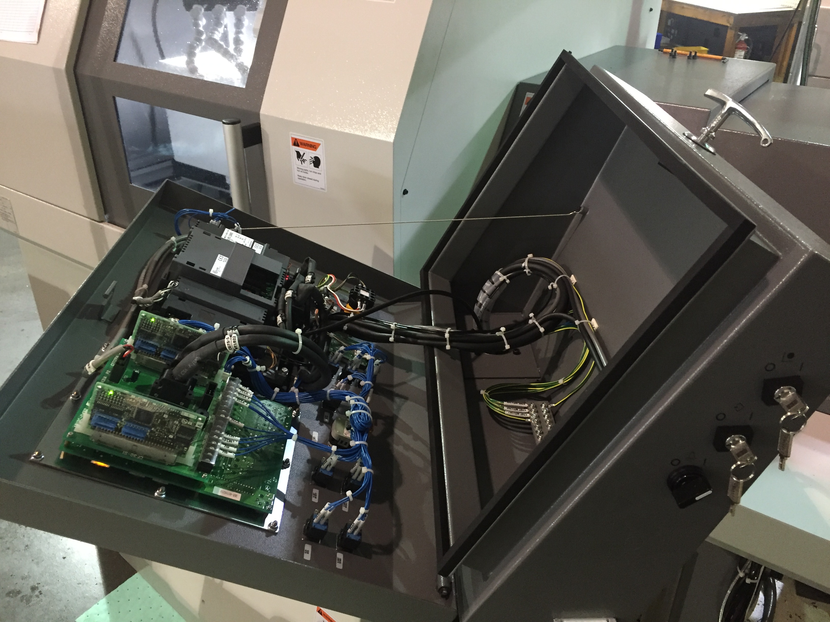
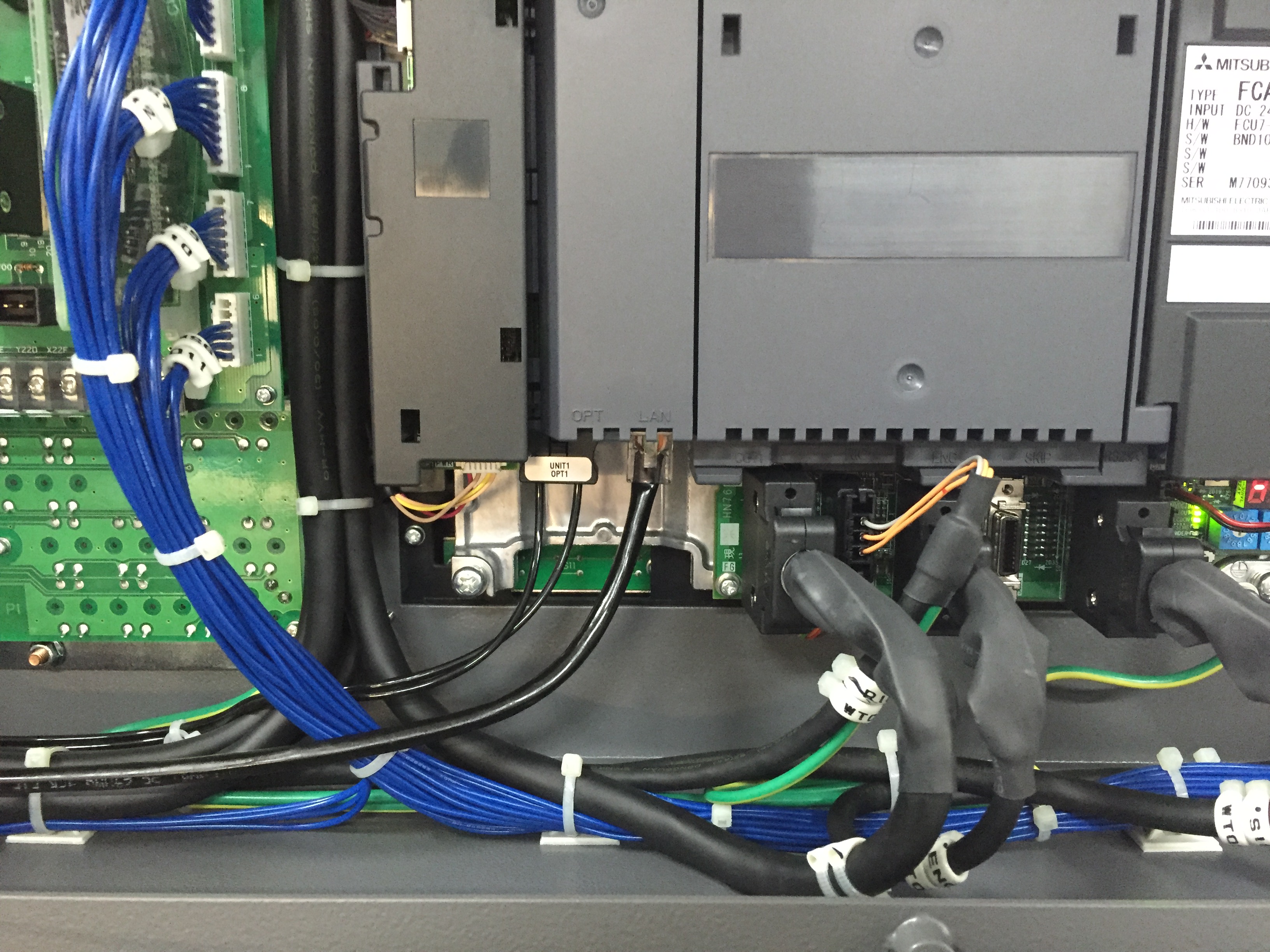
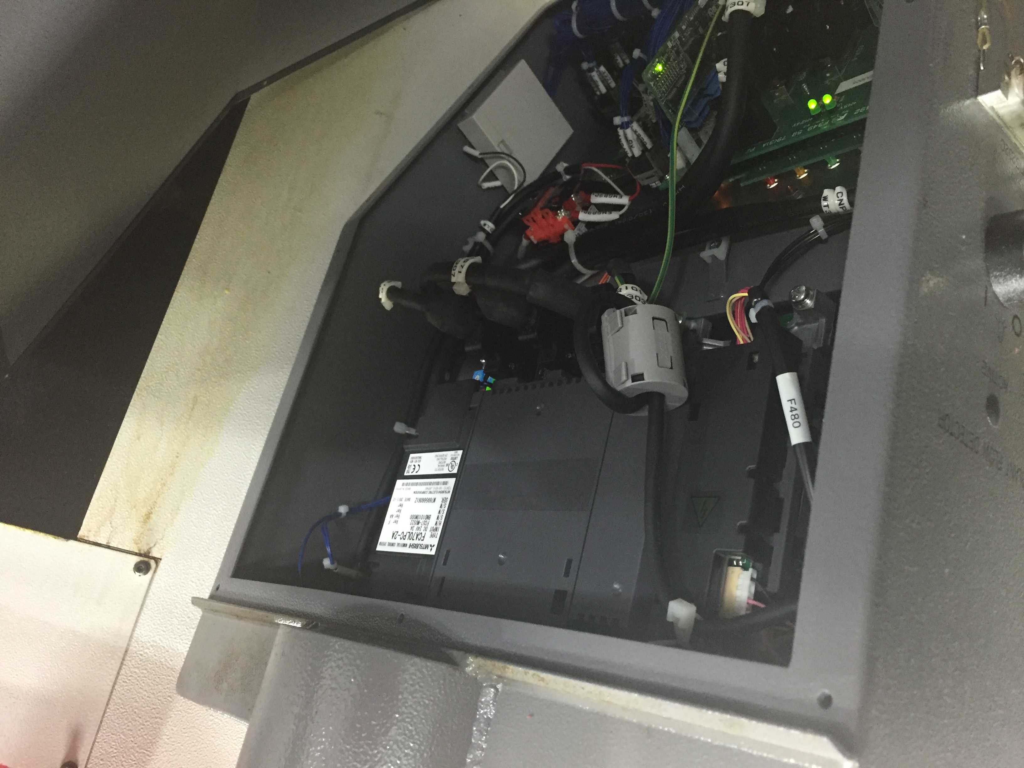
On the Cincom A32, the Mitsubishi NCU board is visible in a similar location:
Prerequisites
Before configuring network settings:
- Firmware meets minimum requirements (see above)
- You have a static IP address assigned for this machine
- You have subnet mask and gateway information from your IT team
- You have physical access to the machine control
Configuration Steps
Step 1: Access Maintenance Mode
Press the MAINT hardkey.
Step 2: Open Interface Diagnostics
Press the I/F DIAG softkey.
Step 3: Enter Password
Type 1001//M and hit the INPUT softkey.
Step 4: Access Parameters
Press the PARAM hardkey.
Step 5: Navigate to Communication Settings
Press the MENU SEL softkey once.
Step 6: Open Basic Communication Settings
Press the BAS COM softkey.
Step 7: Navigate to IP Settings
Press PGDN hardkey until you see "Global IP Address".
⚠️ WARNING: DO NOT ENTER IPs INTO "HMI IP" FIELDS - THIS WILL BRICK YOUR MACHINE!
Step 8: Enter Network Configuration
Enter the following (press INPUT hardkey after each entry):
- Global IP Address: Your assigned static IP (e.g.,
192.168.1.150) - Subnet Mask: Your network's subnet mask (typically
255.255.255.0) - Gateway IP: Your network gateway (if required)
Step 9: Reboot Machine
Reboot the machine for settings to take effect.
Step 10: Test Connection
Ping the IP address you configured from a computer on the same network to verify communication:
ping 192.168.1.150
You should receive replies confirming network connectivity.
Adding Machine in MachineMetrics
Step 1: Navigate to Machine Settings
- Log into MachineMetrics
- Go to Assets → Machines
- Click Add Machine
Step 2: Enter Machine Details
Fill in machine information:
- Machine Name: (e.g., "Citizen L20-VIII")
- Make: Citizen
- Model: (e.g., "L20", "L32", "A32")
- Edge Device: Select your Edge device
Step 3: Select Adapter Type
Choose the appropriate adapter based on your control:
| Control Type | Adapter to Select |
|---|---|
| M700 Series | Citizen M700 |
| M850 Series | Mitsubishi M70 |
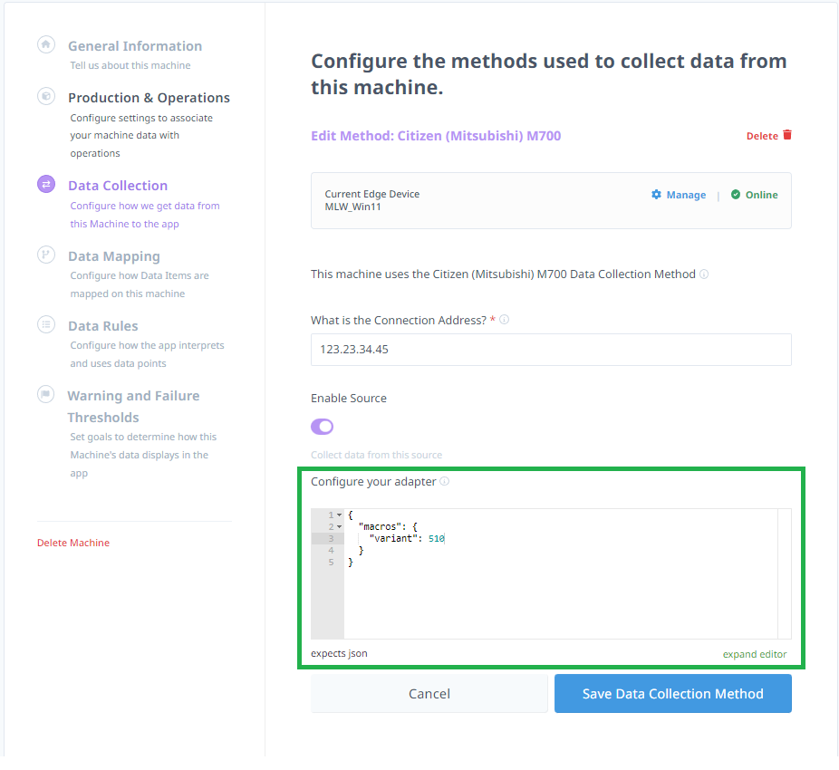
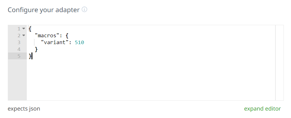
The adapter JSON accepts a macros.variant field to specify which common variable set to read. The default variant is 510:
Step 4: Enter Connection Details
Connection address: <IP address>:<port>
Examples:
- Citizen L20 (M700):
192.168.1.150:683 - Citizen with M850:
192.168.1.150:683
Note: Port number is typically 683 for Citizen machines. Verify on the control network settings if connection fails.
Step 5: Test Connection
- Click Test Connection
- Wait for connection verification
- If successful, click Save
- If failed, verify:
- IP address is correct
- Port number is correct
- Machine is powered on
- Network connectivity exists (try pinging machine)
- Firmware meets minimum requirements
Alternative: I/O Integration
When the native M700 adapter is not available or supplemental signal monitoring is required, Citizen and Miyano machines can be connected using I/O (Digital Input/Output) methods. These use the machine's electrical outputs — stack lights, auxiliary relays, or M-function signals — wired to a MachineMetrics I/O module.
Method 1: Stack Light (Running/In-Cycle Signal)
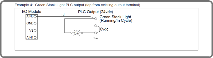
The most common I/O method taps the green stack light output on the PLC output terminal block.
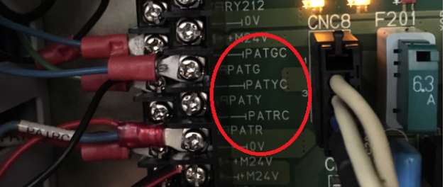
Locating the output terminals:
Stack light outputs on Citizen machines are typically labeled PATGC / PATG (green — running) and PATRC / PATR (red — alarm) on the CNC8 terminal block inside the electrical cabinet.
Wiring diagram:
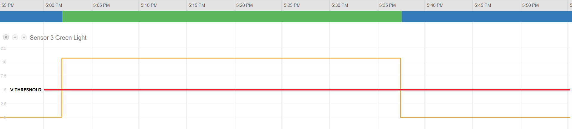
Result in MachineMetrics:
The green light voltage signal drops when the machine stops running, enabling automatic cycle time tracking via threshold detection.
Method 2: Current Transducer (Spindle Load)
A current transducer (CT) clipped around the spindle drive motor cable provides an analog voltage signal proportional to spindle load — useful for detecting cycle activity on machines without accessible digital outputs.
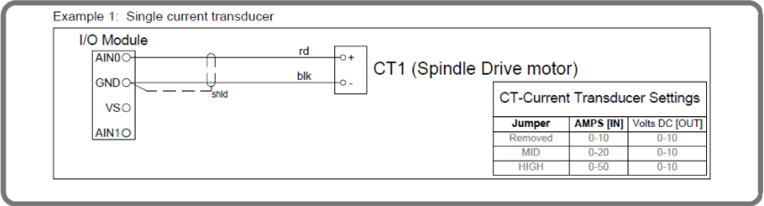
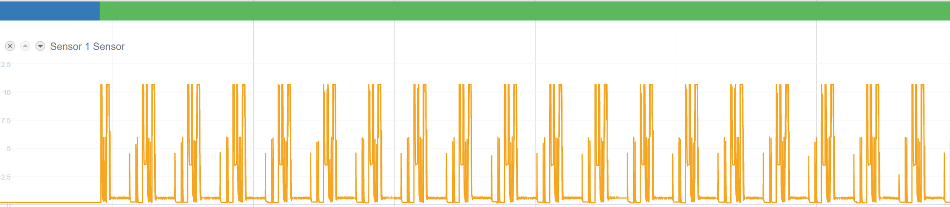
Result in MachineMetrics:
The CT signal produces a voltage waveform that peaks during cutting and drops to near-zero when idle.
Method 3: Bar-Feed Work Count Relay
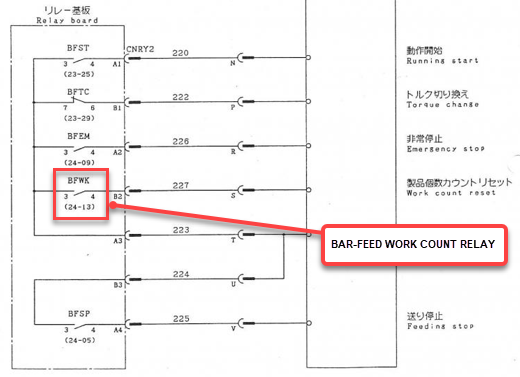
Citizen machines equipped with bar feeders have a Bar-Feed Work Count Relay (BFWK) in the relay board. This relay pulses each time a new bar feed cycle completes, making it ideal for part counting.
Locating the relay:
The BFWK relay is found on the relay board inside the machine, typically at terminals 24-13 on the relay labeled B2.
Method 4: M-Function Relay (Spare M-Code Part Count)
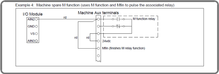
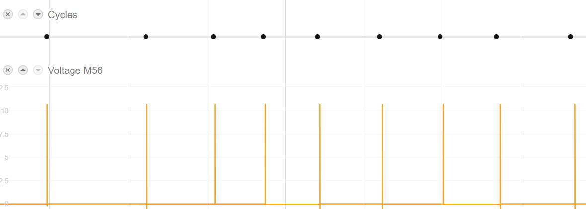
For machines where a dedicated part-count M-code (e.g., M56) is programmed into the NC, the corresponding M-function relay and Mfin signal can be wired to the I/O module as a part-count trigger.
Wiring diagram:
Result in MachineMetrics:
Each M56 pulse is captured as a discrete part-count event.
For full I/O module wiring instructions, see the Digital I/O Connectivity.