IFM IO-Link Connectivity
- Overview
- What is IO-Link
- Supported Devices
- IFM Sensor Catalog
- Prerequisites
- Device Setup
- MachineMetrics Configuration
- Connecting Sensors
- Data Mapping
- Troubleshooting
- Additional Resources
- Getting Help
Overview
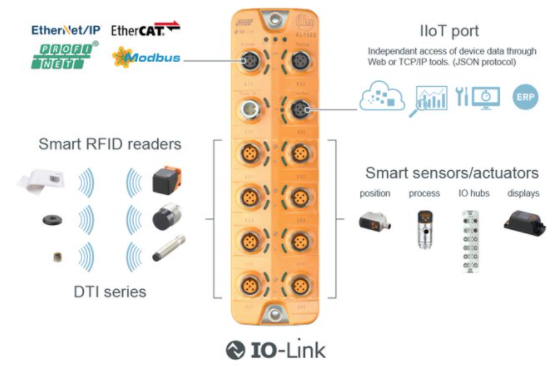
IFM IO-Link master block and sensors. MachineMetrics partners with IFM to connect IO-Link conforming sensors for temperature, pressure, flow, vibration, and other process data collection.
MachineMetrics partners with IFM to provide seamless connectivity to a wide range of IO-Link sensors for industrial data collection. This integration allows you to connect temperature sensors, pressure sensors, flow meters, vibration sensors, and many other smart sensors to capture real-time process data from your production environment.
Key Features:
- Connect any IO-Link conforming sensor to MachineMetrics
- Automatic sensor discovery and configuration
- Support for IFM IO-Link master blocks with IoT ports
- Real-time data collection from multiple sensors
- Cross-manufacturer sensor compatibility (IO-Link standard)
Partnership with IFM:
MachineMetrics has a strategic partnership with IFM to enable connectivity to their extensive portfolio of industrial sensors. All IFM IO-Link sensors are supported through this integration.
What is IO-Link
IO-Link is an open industrial communication protocol standard (IEC 61131-9) that enables intelligent sensors and actuators to communicate with control systems and gateways.
Key Characteristics:
- Device Protocol: Standardizes data exchange between sensors and gateway devices (master blocks)
- Vendor Neutral: Sensors from different manufacturers are cross-compatible with any IO-Link master block
- Point-to-Point Communication: Each sensor connects to a port on the master block
- Bidirectional: Supports both data collection and sensor configuration
What IO-Link is NOT:
- ❌ NOT a data contextualization standard (like MTConnect)
- ❌ NOT a standardized communication protocol between master block and external applications
- ❌ Because of this, MachineMetrics support is limited to specific master blocks
How It Works:
- Sensors connect to individual ports on the IO-Link master block
- Master block communicates with sensors using IO-Link protocol
- Master block exposes sensor data via its own protocol (IoT, EtherNet/IP, Modbus, etc.)
- MachineMetrics Edge connects to the master block to collect sensor data
Supported Devices
Master Blocks
MachineMetrics currently supports:
✅ IFM Master Blocks with IoT Data Port
- IFM AL1350 (IO-Link master, 8 ports, IoT interface)
- IFM AL1352 (IO-Link master, 4 ports, IoT interface)
- Other IFM blocks with dedicated IoT ethernet port
Important Notes:
- ⚠️ Not all IFM blocks have an IoT port - Verify your master block model
- ❌ EtherNet/IP-based blocks cannot be supported via our EtherNet/IP integration
- ⚠️ Modbus-based blocks can be supported as a Modbus integration, but data must be unpacked manually (not recommended) - See Modbus TCP Guide
- 📝 Additional master block models may be supported in the future
Sensors
✅ All IO-Link Conforming Sensors
The integration supports any sensor that conforms to the IO-Link standard, including but not limited to:
IFM Sensors (Extensive Portfolio):
- Temperature sensors
- Pressure sensors
- Flow meters
- Level sensors
- Vibration monitoring sensors
- Position sensors
- Distance sensors
- Humidity sensors
- Photoelectric sensors
- Inductive proximity sensors
Other Manufacturers:
- Balluff sensors
- Sick sensors
- ifm electronic sensors
- Turck sensors
- Any IO-Link compliant sensor
IFM Sensor Catalog
MachineMetrics partners directly with IFM — one of the world's leading industrial sensor manufacturers — so customers can purchase sensors directly from IFM and have them working with MachineMetrics out of the box. Every sensor below is IO-Link enabled and supported by this integration.
Use the part numbers and links below to purchase sensors directly at ifm.com.
IO-Link Master Block
Every IO-Link setup requires a master block — the hub that connects your sensors to the network and passes data to MachineMetrics. MachineMetrics works with any IFM master block that has an IoT port (the Ethernet port running MQTT/JSON). The IoT port is separate from any EtherNet/IP or Modbus ports on the same device.
Start here: The AL1324 is a practical entry point — it supports 4 sensors and is compact enough to mount close to a machine. If you need more sensors, step up to the AL1350 (8 ports).
| Part Number | Description | IO-Link Ports | Interface | Link |
|---|---|---|---|---|
| AL1324 | IO-Link master — entry level | 4 ports (Class A) | IoT (MQTT/JSON) + EtherNet/IP | View on IFM |
| AL1350 | IO-Link master — 8 port | 8 ports (Class A) | IoT (MQTT/JSON) | View on IFM |
| AL1352 | IO-Link master — 8 port, compact | 8 ports (Class A) | IoT (MQTT/JSON) | View on IFM |
Need more than 8 sensors? Multiple master blocks can be deployed on the same network and configured as separate data sources in MachineMetrics. There is no hard limit on the number of master blocks per machine or site.
Browse all IFM IO-Link masters with IoT interface →
Inductive Sensors
Inductive sensors detect the presence or absence of metal objects without physical contact. Common manufacturing uses include confirming tool presence in a spindle, detecting pallet position on a fixture, verifying a chuck is clamped, or checking that a door or guard is closed.
| Part Number | Description | Key Specs | Link |
|---|---|---|---|
| IG6215 | Inductive sensor with IO-Link | M12 housing, 4 mm sensing range, PNP/NPN, IP67, 10–30 VDC | View on IFM |
| IQ2008 | Inductive sensor with IO-Link | Flush mount, IO-Link COM2, compact M8 housing | View on IFM |
| II5984 | Inductive sensor with IO-Link | M18 housing, extended sensing range, IO-Link Rev 1.1 | View on IFM |
Browse all IFM inductive sensors →
Ultrasonic Sensors
Ultrasonic sensors use sound waves to measure distance and detect objects regardless of color, transparency, or surface finish. Common uses include non-contact level measurement in tanks, detecting clear or translucent materials, and measuring the height of stacked parts or material in hoppers.
| Part Number | Description | Key Specs | Link |
|---|---|---|---|
| UGT502 | Ultrasonic sensor with IO-Link | M18 housing, up to 800 mm range, PNP/NPN switching + analog | View on IFM |
| UGT204 | Ultrasonic sensor with IO-Link | M30 housing, 30–350 mm range, 4-pin M12 connector | View on IFM |
| UGT585 | Ultrasonic sensor with IO-Link | Long range up to 2,500 mm, M30 housing, IP67 | View on IFM |
Browse all IFM ultrasonic sensors →
Photoelectric Sensors
Photoelectric sensors use light (visible or laser) to detect the presence, absence, or position of objects. Common uses include part counting on a conveyor, detecting parts in a fixture, confirming a bin is empty, and monitoring machine guarding doors.
| Part Number | Description | Key Specs | Link |
|---|---|---|---|
| OGH700 | Laser diffuse reflection sensor with IO-Link | Sensing range up to 300 mm, M18 housing, Class 1 laser, IP67 | View on IFM |
Browse all IFM photoelectric sensors →
Distance Sensors
Laser distance sensors measure the precise distance to a target and transmit an analog or digital value over IO-Link. Common uses include part dimensional checks, positioning feedback, and detecting stroke position on pneumatic actuators.
| Part Number | Description | Key Specs | Link |
|---|---|---|---|
| O1D100 | Laser distance sensor with IO-Link | 0.2–10 m range, PMD time-of-flight, PNP + analog output, IP67 | View on IFM |
| O1D102 | Laser distance sensor (dark/shiny targets) | Up to 3.5 m range, optimized for black and reflective surfaces, IO-Link | View on IFM |
Browse IFM O1D distance sensors →
Pressure Sensors
Pressure sensors monitor system pressure in hydraulic circuits, coolant lines, lubrication systems, and pneumatic circuits. Tracking pressure in real time helps detect leaks, blockages, or pump failures before they cause machine downtime.
| Part Number | Description | Key Specs | Link |
|---|---|---|---|
| PN7070 | Pressure sensor with display and IO-Link | 0–400 bar range, 4-digit LED display, G1/4 process connection, IP65/67, ±0.5% accuracy | View on IFM |
Browse all IFM pressure sensors →
Flow Meters
Flow sensors monitor the flow rate of coolant, cutting fluid, hydraulic oil, lubrication, or compressed air. Loss of flow is one of the most common causes of tool breakage and unplanned downtime — IO-Link flow meters let MachineMetrics alert on low or zero flow before damage occurs.
| Part Number | Description | Key Specs | Link |
|---|---|---|---|
| SBN232 | Mechatronic flow meter with IO-Link | 0.1–10 gpm, water and oil media, integrated temperature measurement, NPT connection | View on IFM |
| SBN246 | Mechatronic flow meter with IO-Link | 0.1–50 gpm, higher flow range for larger coolant lines, NPT connection | View on IFM |
| SA6010 | Thermal flow sensor with IO-Link | Insertion style, 0.1–6,150 gpm (liquids), also supports gases, -4–212 °F | View on IFM |
Level Sensors
Level sensors detect whether a tank, reservoir, or bin has reached a set fill level (point level) or measure the continuous level of liquid or bulk material. Common uses include coolant tank monitoring, chip conveyor bin full alerts, and wash system fluid levels.
| Part Number | Description | Key Specs | Link |
|---|---|---|---|
| LMT100 | Point level sensor with IO-Link | Impedance spectroscopy, sanitary design, stainless steel, immune to foam and deposits | View on IFM |
| LMT102 | Point level sensor with IO-Link | Shorter insertion length variant of LMT100, same sensing technology | View on IFM |
Browse all IFM level sensors →
Temperature Sensors
Temperature sensors track the temperature of coolant, hydraulic fluid, spindle bearings, motors, and process media. Rising temperatures often indicate inadequate lubrication, blocked cooling circuits, or impending equipment failure — IO-Link temperature sensors feed this data directly into MachineMetrics for alerting and trend analysis.
| Part Number | Description | Key Specs | Link |
|---|---|---|---|
| TCC501 | Self-monitoring temperature transmitter with IO-Link | ±0.36 °F accuracy, dual sensing elements for self-verification, 316 SS, IP69K, -13–320 °F | View on IFM |
Browse all IFM temperature sensors →
RFID
IFM IO-Link RFID systems enable automatic identification of tooling, pallets, fixtures, and work-in-progress (WIP) on the shop floor. Data is read directly into MachineMetrics, enabling traceability, cycle time tracking per job, and automatic production order association without manual barcode scanning.
| Part Number | Description | Key Specs | Link |
|---|---|---|---|
| DTI801 | RFID UHF compact unit with IO-Link | 860–960 MHz UHF, read range up to 700 mm, M12 connector, IP67 | View on IFM |
| DTI425 | RFID HF read/write head with IO-Link | 13.56 MHz HF, short-range precision reading, M12 connector | View on IFM |
Speed Sensors
Speed sensors monitor rotational speed of motors, spindles, conveyors, and other rotating equipment. MachineMetrics can use speed data to confirm machines are running at the correct RPM, detect stalls or unexpected stops, and correlate speed with quality and cycle time data.
| Part Number | Description | Key Specs | Link |
|---|---|---|---|
| DI5001 | Compact speed monitor with IO-Link | 0.08–400 Hz setting range, M18 housing, inductive sensing, configurable window/single/two-point mode | View on IFM |
Browse all IFM speed sensors →
Purchasing: All IFM sensors can be purchased directly at ifm.com. IFM also offers application engineering support to help select the right sensor for your specific use case. Contact IFM at 1-800-441-8246 or visit their website to get a quote.
Prerequisites
Before setting up IO-Link connectivity, ensure you have:
Hardware Requirements:
- IFM IO-Link master block with IoT port
- IO-Link sensors (IFM or other manufacturers)
- Network cable (Cat5e or Cat6) for master block
- MachineMetrics Edge device on the same network
- Appropriate M12 cables for sensor connections
Network Requirements:
- Available static IP address on your network
- Network switch or router with available port
- Ethernet access between Edge device and master block
Software Requirements:
- IFM's configuration software (for initial setup)
- Download from: https://www.ifm.com/us/en/category/095_010_010
- MachineMetrics account with IO-Link integration enabled
Access Requirements:
- Physical access to install master block and sensors
- Network configuration permissions
- Knowledge of sensor mounting locations
Device Setup
IFM Master Block Configuration
Step 1: Physical Installation
- Mount the IFM master block on DIN rail or suitable location
- Connect power supply to master block (24V DC typical)
- Verify power LED illuminates
Step 2: Identify IoT Port
IFM master blocks support multiple protocols on different physical ports:
- IoT Port - Required for MachineMetrics integration (Ethernet with RJ45)
- EtherNet/IP Port - NOT compatible with this integration
- Modbus Port - NOT recommended (requires manual configuration) - See Modbus TCP Guide if needed
Critical: Ensure you connect the IoT port (not EtherNet/IP or Modbus port) to your network.
Step 3: Connect to Network
- Connect network cable from the IoT port to your network switch
- Verify link lights on Ethernet port are active
Network Configuration
Step 1: Install IFM Configuration Software
- Download IFM's configuration software from: https://www.ifm.com/us/en/category/095_010_010
- Install on a PC connected to the same network
- Launch the configuration tool
Step 2: Discover Master Block
- Open IFM configuration software
- Click Scan or Discover Devices
- Locate your master block in the list (note MAC address if multiple devices)
Step 3: Assign Static IP Address
- Select your master block in the configuration software
- Navigate to Network Settings or IoT Port Configuration
- Set IP Configuration to Static (Manual)
- Enter network information:
- IP Address: (e.g., 192.168.1.150)
- Subnet Mask: (e.g., 255.255.255.0)
- Gateway: (e.g., 192.168.1.1)
- Click Apply or Write Configuration
- Document the IP address for MachineMetrics configuration
Step 4: Verify Configuration
- Disconnect configuration PC
- Reconnect to network
- Verify master block is accessible at the assigned IP address
- Test with ping:
ping 192.168.1.150
Sensor Port Configuration
Step 1: Set Port Operating Modes
IFM master blocks allow individual port configuration:
- In IFM configuration software, navigate to Port Configuration
- For each port you'll use, set mode to IO-Link
- Other modes (Digital Input, Digital Output) will not work with this integration
Step 2: Connect Sensors
- Connect IO-Link sensors to master block ports using M12 cables
- Ports are numbered (typically Port 1 - Port 8 or Port 1 - Port 4)
- Document which sensor is connected to which port
Step 3: Verify Sensor Detection
- In IFM configuration software, view Port Status
- Verify each connected sensor shows:
- Status: Connected or Active
- Vendor ID: Numeric identifier for manufacturer
- Device ID: Numeric identifier for sensor model
- Note the Vendor ID and Device ID for each sensor (useful for troubleshooting)
MachineMetrics Configuration
Automatic Configuration
In most cases, the IO-Link integration will automatically configure itself based on IODD (IO Device Description) files.
Step 1: Add Machine in MachineMetrics
- Log into MachineMetrics at app.machinemetrics.com
- Navigate to Assets → Machines
- Click Add Machine
- Enter machine/sensor details:
- Name: (e.g., "Hydraulic-Press-Sensors" or "Assembly-Station-01")
- Type: (Select appropriate type or "Sensor Station")
- Click Next
Step 2: Select IO-Link Integration
- In Data Collection Method, select IO-Link or IFM IoT
- If not visible, contact MachineMetrics support
Step 3: Enter Master Block IP Address
- Enter the IFM master block's IP address (e.g., 192.168.1.150)
- The connector will automatically discover connected sensors
Step 4: Save and Test
- Click Test Connection
- MachineMetrics will:
- Connect to the master block
- Discover connected sensors
- Automatically create data items for each sensor
- If successful, click Save
Note: The IO-Link connector automatically discovers and configures sensors. No manual adapter script configuration is required.
Data Item Naming Convention
Automatically-configured sensors produce data items with a specific naming structure:
Format:
iolink_p<n>_<vendorid>_<deviceid>_<subindex>_<shortname>
Components:
<n>- Port number (1-8 or 1-4, depending on master block)<vendorid>- Manufacturer's vendor ID<deviceid>- Specific device/model ID<subindex>- Data item index within sensor's process data (starts at 1)<shortname>- Truncated, processed display name for identification
Example: IFM Humidity Air Sensor
IFM humidity/temperature sensor (Vendor ID: 310, Device ID: 1337) connected to Port 2:
iolink_p2_310_1337_1_humidity
iolink_p2_310_1337_2_temperature
iolink_p2_310_1337_3_devicestatus
Explanation:
p2- Connected to Port 2310- IFM vendor ID1337- Humidity sensor device ID1,2,3- Sub-indexes for different measurementshumidity,temperature,devicestatus- Shortened names
Data Transformation
The IO-Link connector uses automatic sensor discovery and configuration. Manual configuration of process data, bit offsets, gradients, and offsets is not required.
If you need to transform or manipulate the IFM data items to solve your specific use case, use transform adapter scripts to process the automatically discovered data items.
See the Transform Adapter Scripts Guide for information on:
- Renaming data items
- Applying mathematical transformations
- Combining multiple data items
- Creating custom variables from sensor data
Connecting Sensors
Step 1: Plan Sensor Placement
- Identify measurement points on your equipment
- Determine appropriate sensor types for each point
- Plan cable routing from sensors to master block
Common Use Cases:
| Application | Sensor Type | Example IFM Models |
|---|---|---|
| Hydraulic Pressure | Pressure Sensor | PN, PT series |
| Coolant Temperature | Temperature Sensor | TN, TA series |
| Air Flow Rate | Flow Sensor | SM, SD series |
| Tool Vibration | Vibration Sensor | VSE, VSP series |
| Part Position | Distance Sensor | O1D, O5D series |
| Coolant Level | Level Sensor | LR, LK series |
| Spindle Temperature | Temperature Sensor | TN series |
Step 2: Mount Sensors
- Install sensors at measurement points
- Follow manufacturer's installation guidelines
- Ensure proper orientation (especially for flow sensors)
- Verify sensor is within operating range
Step 3: Connect M12 Cables
- Use appropriate M12 cables (4-pin or 5-pin depending on sensor)
- Connect sensor M12 connector to cable
- Route cable to master block location
- Connect cable to master block port
Step 4: Label Connections
Document each connection:
- Port number
- Sensor type
- Measurement location
- Cable routing
Data Mapping
Step 1: Verify Data Collection
- Navigate to machine page in MachineMetrics
- Go to Diagnostics tab
- Verify data items are populating with values
- Check data item names match expected format
Step 2: Configure Data Mapping
- Go to Machine Settings → Data Mapping tab
- Map IO-Link data items to MachineMetrics data types:
Example Mappings:
| IO-Link Data Item | MachineMetrics Type | Subtype |
|---|---|---|
iolink_p1_310_1337_1_humidity | SAMPLE | Custom (Humidity %) |
iolink_p1_310_1337_2_temperature | SAMPLE | TEMPERATURE |
iolink_p2_310_2001_1_pressure | SAMPLE | PRESSURE |
iolink_p3_310_2500_1_flow | SAMPLE | Custom (Flow Rate) |
- Set appropriate Component (Machine, Coolant, Hydraulic, etc.)
- Add display names if needed
- Click Save
Step 3: Configure Units (If Needed)
- Note the units for each sensor from datasheet
- Include units in display names if not automatically included
- Example: "Coolant Temperature (°C)" or "Hydraulic Pressure (bar)"
Step 4: Set Up Alerts (Optional)
- Navigate to Automations & Workflows
- Create alerts based on sensor thresholds:
- High temperature warnings
- Low pressure alerts
- Vibration limit notifications
Troubleshooting
Connection Issues
Problem: Cannot Connect to Master Block
Possible causes:
- Incorrect IP address
- Network connectivity issue
- Wrong port used (IoT port vs EtherNet/IP port)
- Firewall blocking communication
Solutions:
- Verify IP address is correct (check IFM configuration software)
- Test network connectivity with ping
- Verify IoT port is used (not EtherNet/IP or Modbus port)
- Check that IoT port is assigned static IP
- Verify Edge device and master block are on same network/subnet
Problem: Intermittent Connection
Possible causes:
- Network instability
- DHCP IP address changing (if not static)
- Cable issues
Solutions:
- Use static IP address (not DHCP)
- Check network cable quality
- Verify network switch port is functioning
- Monitor network latency with continuous ping
Sensor Detection Issues
Problem: Sensors Not Detected
Possible causes:
- Sensor not properly connected
- Port not set to IO-Link mode
- Incompatible sensor
- Faulty cable
Solutions:
- Verify sensor connection (check M12 connector)
- Check port mode in IFM configuration software (must be IO-Link)
- Verify sensor is IO-Link compatible (check datasheet)
- Test with different M12 cable
- Try sensor on different port
Problem: Sensor Detected But No Data
Possible causes:
- IODD file not found
- Sensor in error state
- Process data configuration incorrect
Solutions:
- Check MachineMetrics adapter logs for IODD errors
- Verify sensor status LED (if present)
- Check sensor configuration in IFM software
- Try manual configuration with sensor datasheet
- Contact MachineMetrics support for IODD file availability
Data Issues
Problem: Data Values Incorrect
Possible causes:
- Missing or incorrect gradient/offset
- Wrong data type (int vs uint)
- Incorrect bit offset or length
Solutions:
- Verify gradient and offset from sensor datasheet
- Check data type matches sensor specifications
- Review manual configuration for typos
- Compare raw values in IFM software vs MachineMetrics
- Apply correct scaling factors
Problem: Data Items Not Appearing
Possible causes:
- Auto-configuration failed
- IODD file unavailable
- Data items not exported
Solutions:
- Check adapter logs for errors
- Verify IODD file exists for your sensor
- Try manual configuration
- Ensure data-items list includes sensor names
- Check if sensor is in IODD library
Master Block Issues
Problem: Master Block Not Responding
Possible causes:
- Power loss
- Network configuration lost
- Firmware issue
Solutions:
- Check power supply to master block
- Verify power LED is illuminated
- Reconfigure network settings with IFM software
- Reset master block to factory defaults (last resort)
- Update master block firmware if available
Additional Resources
MachineMetrics Resources:
- Transform Adapter Scripts Guide - Advanced data transformation
- Machine Settings Guide - Configure data mapping
- Connectivity Overview - Compare connectivity methods
IFM Resources:
- IFM Website: https://www.ifm.com
- IFM Software Downloads: https://www.ifm.com/us/en/category/095_010_010
- IFM Sensor Catalog: https://www.ifm.com/us/en/products
- IO-Link Technology Overview: https://www.ifm.com/us/en/shared/technologies/io-link
IO-Link Standard:
- IO-Link Technology: https://io-link.com/
- IO-Link Specification: IEC 61131-9
- IODD File Repository: https://ioddfinder.io-link.com/
Related Guides:
- Edge Device Setup - Configure MachineMetrics Edge
- Network Requirements - Firewall configuration
Getting Help
MachineMetrics Support:
- Email: support@machinemetrics.com
- Phone: 844-822-0664
Before Contacting Support:
- Note IFM master block model number
- Document connected sensor models and port numbers
- Verify network configuration (IP address, connectivity)
- Capture screenshots of IFM configuration software
- Note Vendor ID and Device ID for problematic sensors
- Check adapter logs in MachineMetrics
Information to Provide:
- IFM master block model and firmware version
- List of connected sensors (make, model, port number)
- Network configuration (IP address, subnet, gateway)
- Adapter configuration (YAML)
- Description of issue and troubleshooting steps taken
- Screenshots of IFM software showing sensor status
For IODD Issues:
- Provide Vendor ID and Device ID
- Note sensor manufacturer and model number
- Include sensor datasheet (if available)
- Describe expected vs actual data values