Heidenhain TNC Connectivity
- Overview
- Applicable Controls
- Prerequisites
- OPC-UA (Option 56)
- Network Configuration
- MachineMetrics Connector Setup
- Part Counting Configuration
- Troubleshooting
- Additional Resources
- Getting Help
Overview
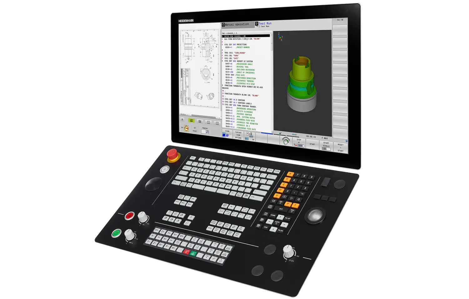
Heidenhain TNC control panel. Heidenhain controls (iTNC 530, TNC 530, TNC 640, TNC 730, TNC7) connect via proprietary Ethernet protocol or OPC-UA (Option 56), providing real-time machine status and PLC data access for part counting.
MachineMetrics connects to Heidenhain TNC controls using a proprietary connector that communicates directly with the control over Ethernet. This native integration provides real-time machine data including status, programs, tools, and part counts.
Key Features:
- Direct Ethernet communication with TNC controls
- Real-time machine status and production data
- PLC data table access for part counting
- Support for iTNC 530 / TNC 530, TNC 640, and TNC 730 controls
- Alternative OPC-UA connectivity available (Option 56) for TNC 640 / TNC 730
- No additional hardware required (Ethernet connection only)
Applicable Controls
This guide covers connectivity for the following Heidenhain controls:
Supported Controls:
- iTNC 530 / TNC 530 - All versions
- TNC 640 - Requires connectivity option (see below)
- TNC 730 - Requires connectivity option (see below)
- TNC7 — OPC-UA Option 56 per Heidenhain documentation (use OPC-UA path in MachineMetrics; see OPC-UA (Option 56))
Recommended Connectivity Options for TNC 640 / TNC 730
For TNC 640 and TNC 730 controls, we recommend:
✅ Recommended: OPC-UA Option 56
Option 56 provides better data quality, more comprehensive data access, and easier part counting configuration compared to Option 18. If you need to purchase a connectivity option, choose Option 56 instead of Option 18. See the HEIDENHAIN OPC UA NC Server product page for details.
Available Options:
| Option | Description | Recommendation | Data Quality | Part Counting |
|---|---|---|---|---|
| Option 56 (OPC-UA) | OPC-UA server connectivity | ✅ Recommended | Better data access and quality | Easier configuration |
| Option 18 | Proprietary Ethernet protocol | ⚠️ Alternative if Option 56 unavailable | Standard data access | Requires PLC WORD mapping |
90-Day Free Trial:
Customers can try OPC-UA Option 56 for free for 90 days. Contact Heidenhain directly (not MachineMetrics) to request the trial license.
iTNC 530 / TNC 530:
The iTNC 530 / TNC 530 does not require any additional options for connectivity.
Alternative Connectivity for TNC 640 / TNC 730:
If neither option is available, you can use the proprietary Heidenhain connector (this guide). However, we strongly recommend upgrading to Option 56 for better data quality.
Checking Installed Options (SIK Page):
To verify which options are installed on your control:
For iTNC 530 / TNC 530:
-
Power on the control and let it boot fully
-
Press the Programming and Editing operating mode softkey (right-arrow icon at the top-right of the softkey panel)

-
Press the MOD key

-
Press MOD again → navigate to Machine parameters / Diagnosis (menu wording varies by software version)
-
Choose Option management or Software options
-
Cursor into the input field and type SIK on the keyboard
-
Press ENT
For TNC 640 / TNC 730:
- Power on the control and let it boot fully
- Press the Programming and Editing operating mode softkey (right-arrow icon)
- Press the MOD key
- Press MOD again → navigate to Machine parameters / Diagnosis (menu wording varies)
- Choose Option management or Software options
- Cursor into the input field and type SIK on the keyboard
- Press ENT
You'll see the SIK page listing installed options and license status (Option 18, Option 56, etc.).
What to Look For:
- Option 56 (OPC-UA) - ✅ Recommended for TNC 640/730 (better data quality)
- Option 18 - ⚠️ Alternative connectivity option
- Check the license status shows as active/enabled
Notes:
- You typically need service-level access or higher to enter or change SIK codes; viewing may be allowed at lower access levels
- On some builds, step 3 is labeled Diagnosis → Software options instead of machine parameters
- If typing SIK does nothing, you're either in the wrong menu depth or logged in with insufficient access rights
- A keyboard is required - softkeys alone won't expose the SIK field
Prerequisites
Before beginning setup, ensure you have:
Hardware Requirements:
- Heidenhain iTNC 530 / TNC 530, TNC 640, or TNC 730 control
- Ethernet port on the control:
- iTNC 530 / TNC 530: Standard (no option required)
- TNC 640 / TNC 730: Requires connectivity option
- Recommended: OPC-UA Option 56 (better data quality)
- Alternative: Option 18 (if Option 56 unavailable)
- Network cable (Cat5e or Cat6)
- MachineMetrics Edge device on the same network
💡 Tip: For TNC 640/730, request a 90-day free trial of Option 56 from Heidenhain before purchasing.
Network Requirements:
- Available IP address on company network (static or DHCP)
- Network switch or router with available port
- Access to control's network configuration menu
- Ping access between Edge device and machine
Access Requirements:
- Physical access to the machine control
- Knowledge of machine's network configuration (if applicable)
- Administrator or operator password (if password protection enabled)
OPC-UA (Option 56)
For TNC 640, TNC 730, TNC7, and related controls with Option 56 (OPC-UA NC Server), add the machine in MachineMetrics as OPC-UA (not the Heidenhain proprietary connector). Use the Heidenhain OPC UA Information Model documentation for the authoritative node layout and minimum NC software for each Core Information Model version — see HEIDENHAIN OPC UA NC Server (downloads and revision history).
Software version and information model
Heidenhain ties each Core Information Model revision to minimum NC software builds by product line. The table below is a short excerpt of what Heidenhain publishes (check the current PDF on their site before you deploy).
| Core information model | Product examples | Minimum NC software (per Heidenhain) |
|---|---|---|
| 1.00 | TNC 640 | 34059x-10 |
| 1.01 | TNC 640; TNC 620 | 34059x-11; 81760x-08 |
| 1.07 (current model doc, 2026) | TNC7; TNC7 basic; TNC7 go | e.g. 817620-20, 817621-20, 817625-20; 81762x-20 (TNC7 go) |
Important context from Heidenhain’s documentation:
- NC software 19 and later are only for TNC7 products.
- Further development of TNC 640 and TNC 620 is discontinued — newer information-model features are driven by TNC7; confirm support for your exact control with Heidenhain if you are not on TNC7.
If your NC software is older than the row required for the nodes you need, upgrade the control (or use the proprietary Heidenhain connector path in this guide where supported).
Namespace, browse paths, and channel
Before production use:
- Namespace index — Example scripts often use
ns=3, which is typical for TNC 640 / TNC 730 / TNC7, but it is not guaranteed for every firmware build. In UaExpert, browse Objects → Machine → … and confirm the NodeId prefix (ns=) on a known node. - Browse paths vs. fixed NodeIds — Heidenhain recommends BrowsePaths aligned with BrowseName hierarchy from the Core Information Model where possible; string paths are more stable across machines of the same control generation than opaque numeric identifiers.
- Channel — The sample script targets channel 0 only (
Machine/Channels/0/...). Multi-channel machines need duplicated or merged tag sets per channel.
Default OPC-UA security on the control may require Sign with Basic256Sha256 (as in the sample below); align with what the server advertises and with OPC-UA Connectivity Guide settings in MachineMetrics.
Sample OPC-UA adapter script
Example Transform Adapter Script for a single-channel Heidenhain NC with Core Information Model v1.07-style paths. Verify namespace, security, and paths against your control with UaExpert before deploying.
# Heidenhain OPC UA NC Server — Option 56 (Core Information Model v1.07)
# Single-channel machine (channel 0)
#
# NAMESPACE NOTE: All paths use ns=3. This is typical for TNC 640/TNC 730/TNC7
# controls but is NOT guaranteed. Verify the correct namespace index for your
# specific control generation using UaExpert before deploying.
# Browse to: Objects > Machine > ... and inspect the NodeId ns= value on any node.
#
# BROWSE PATH NOTE: Heidenhain recommends using BrowsePaths (not hardcoded NodeIds).
# The string paths below follow the BrowseName hierarchy from the Core Information
# Model and should be stable across machines of the same control generation.

version: 2
security-mode: Sign
security-policy: Basic256Sha256

# ─── TAGS ────────────────────────────────────────────────────────────────────

tags:
  # Program execution state — NCProgramStateMachineType CurrentState
  # Values: NotSelected, Idle, Running, Stopped, Interrupted, Finished, Error
  exec-state:
    path: ns=3;s=Machine/Channels/0/Program/ExecutionState/CurrentState

  # Active program name
  prog-name:
    path: ns=3;s=Machine/Channels/0/Program/Name

  # Universal workpiece counter (FUNCTION COUNT in NC program)
  part-counter:
    path: ns=3;s=Machine/Channels/0/Counter/CurrentValue

  # Operating mode — NCOperatingMode enum
  # Values (numeric): Manual=0, Handwheel=1, MDI=2, SingleStep=3, Automatic=4, Other=5
  operating-mode:
    path: ns=3;s=Machine/Channels/0/OperatingMode

  # Feed override (%)
  feed-override:
    path: ns=3;s=Machine/Channels/0/FeedOverride

  # Speed (spindle) override (%)
  speed-override:
    path: ns=3;s=Machine/Channels/0/SpeedOverride

  # Actual feed rate (mm/min)
  actual-feed:
    path: ns=3;s=Machine/Channels/0/ActualFeed

  # Spindle in motion (boolean)
  spindle-in-motion:
    path: ns=3;s=Machine/Channels/0/Spindle/InMotion

  # Spindle nominal speed (RPM)
  spindle-speed:
    path: ns=3;s=Machine/Channels/0/Spindle/NominalSpeed

  # Current tool name
  tool-name:
    path: ns=3;s=Machine/Channels/0/CurrentTool/Name

  # NC state machine — overall control connection/availability state
  # Values: NCIsNotConnected, NCIsConnected, NCIsBooted, NCIsAvailable,
  #         NCIsInitializing, NCIsShuttingDown
  nc-state:
    path: ns=3;s=Machine/State/CurrentState

# ─── VARIABLES ───────────────────────────────────────────────────────────────

variables:
  # Execution state derived from NCProgramStateMachine CurrentState string value
  execution:
    - source: exec-state
    - state:
      - ACTIVE: this == "Running"
      - INTERRUPTED: this == "Interrupted" or this == "Stopped" or this == "Error"
      - READY: this == "Idle" or this == "Finished" or this == "NotSelected"

  # Controller mode derived from NCOperatingMode enum
  controller-mode:
    - source: operating-mode
    - state:
      - AUTOMATIC: this == 4
      - MANUAL_DATA_INPUT: this == 2
      - MANUAL: this == 0 or this == 1
      - SEMI_AUTOMATIC: this == 3

  # Part count — pass through cumulative counter value
  part-count:
    - source: part-counter

  # Feed override — pass through
  feedrate-ovr:
    - source: feed-override

  # Speed override — pass through
  speed-ovr:
    - source: speed-override

  # Actual feed rate — pass through
  feed-rate:
    - source: actual-feed

  # Spindle speed — pass through
  spindle-rpm:
    - source: spindle-speed

  # Program name — pass through
  program-name:
    - source: prog-name

  # Tool name — pass through
  tool-id:
    - source: tool-name

  # NC state — pass through for diagnostics
  nc-connection-state:
    - source: nc-state

  # Spindle in motion — pass through
  spindle-running:
    - source: spindle-in-motion

# ─── DATA ITEMS ──────────────────────────────────────────────────────────────

data-items:
  - execution
  - controller-mode
  - part-count
  - program-name
  - tool-id
  - feed-rate
  - feedrate-ovr
  - speed-ovr
  - spindle-rpm
  - spindle-running
  - nc-connection-state
In MachineMetrics, complete OPC-UA machine setup (endpoint URL, credentials, adapter script) using the OPC-UA Connectivity Guide.
Network Configuration
Connecting to Company Network
The Heidenhain control must be connected to your company network to communicate with the MachineMetrics Edge device.
Step 1: Physical Connection
- Locate the Ethernet port on the Heidenhain control
- iTNC 530 / TNC 530: Typically on rear of control panel
- TNC 640 / TNC 730: On control panel or machine electrical cabinet
- Connect network cable from control to network switch/router
- Verify link lights on Ethernet port are active
Step 2: Access Network Settings
For iTNC 530 / TNC 530:
-
Press the Programming and Editing operating mode softkey (the right-arrow icon at the top-right of the softkey panel)
-
Press the MOD key on the control keyboard
-
Enter password NET123 then press ENT to access the network settings menu
-
Navigate to Network or Ethernet Settings
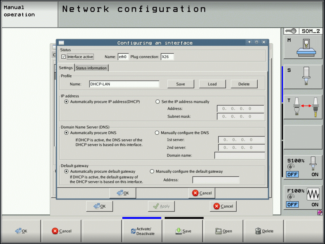
iTNC 530 network configuration dialog (Programming & Editing mode → MOD → NET123 → Network). Select Automatically procure IP address (DHCP) or Set the IP address manually and enter the Address and Subnet mask. Click OK → Apply → Save to commit.
For TNC 640 / TNC 730:
- Press the Heidenhain button (logo button) to bring up the Linux menu
- Navigate to Network Settings or Ethernet Settings
Configuring Network Settings
For Static IP Address (Recommended):
- In Network Settings, select Manual or Static IP
- Enter the following network information:
- IP Address: (e.g., 192.168.1.100)
- Subnet Mask: (e.g., 255.255.255.0)
- Gateway: (e.g., 192.168.1.1)
- DNS Server: (optional, e.g., 192.168.1.1 or 8.8.8.8)
- Save settings and reboot control if prompted
For DHCP (Dynamic IP):
- In Network Settings, select DHCP or Automatic
- Control will automatically obtain IP address from network
- Note the assigned IP address for later use
- Recommended: Reserve this IP in your DHCP server to prevent changes
Important Network Configuration Notes:
- Use static IP or reserved DHCP to ensure consistent connectivity
- Ensure IP address is on same subnet as Edge device
- Document the IP address for MachineMetrics configuration
- Verify no IP conflicts exist on the network
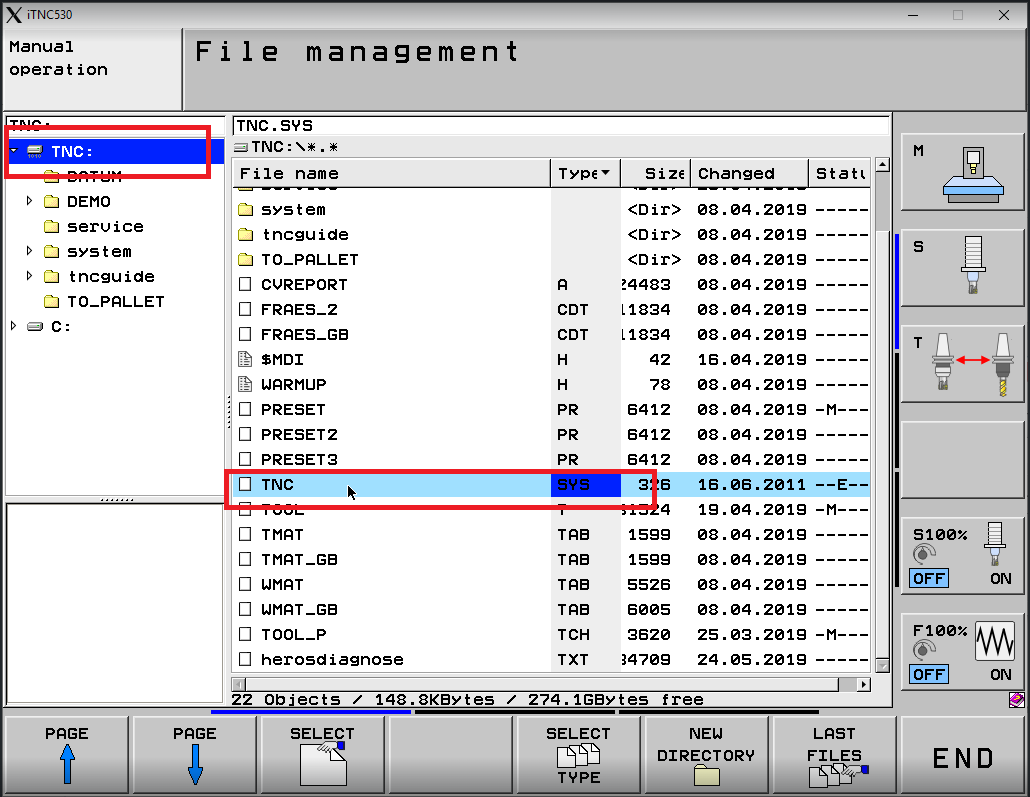
iTNC 530 alternative — editing TNC.SYS directly: Network settings can also be viewed and modified via the File Management screen. Press PGM MGT, navigate to
TNC:\, and locate the TNC.SYS file (type SYS). This file stores the network configuration and can be edited in text mode if the graphical network menu is not accessible.
Testing Network Connection
Step 1: Verify IP Configuration
On the Heidenhain control:
- Navigate to Network Settings
- Verify IP address is displayed and valid
- Check connection status shows "Connected" or "Active"
Step 2: Test from Control (if available)
Some Heidenhain controls have built-in network diagnostics:
- Access Network Settings → Diagnostics (if available)
- Try pinging the Edge device IP address
- Verify successful response
Step 3: Test from Edge Device
From the Edge device or another computer on the network:
ping [MACHINE-IP-ADDRESS]
Example:
ping 192.168.1.100
Expected Result: Continuous successful ping responses with low latency (< 10ms typical)
MachineMetrics Connector Setup
Adding Machine in MachineMetrics
Step 1: Create Machine Record
- Log into MachineMetrics at app.machinemetrics.com
- Navigate to Assets → Machines
- Click Add Machine
- Enter machine details:
- Machine Name: (e.g., "Hermle-C40U-01")
- Machine Type: (Mill, Machining Center, etc.)
- Make: (e.g., Hermle, DMG Mori, Starrag)
- Model: (e.g., C40 U, DMU 50, etc.)
- Serial Number: (optional but recommended)
- Click Next
Step 2: Select Edge Device
- Choose the Edge device that will connect to this machine
- Ensure Edge device is on same network as the Heidenhain control
- Click Next
Heidenhain Connector Configuration
Step 1: Select Connection Method
- In Data Collection Method, select Heidenhain
- If "Heidenhain" is not visible in the dropdown, contact MachineMetrics support
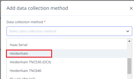
Select Heidenhain from the Data Collection Method dropdown. If you have a TNC 640 with Option 56 (OPC-UA), use the OPC-UA connector instead — see the OPC-UA guide.
Step 2: Enter Machine IP Address
- Enter the Heidenhain control's IP address (e.g., 192.168.1.100)
- The connector will automatically detect the control type and available data
Step 3: Save Configuration
- Review the IP address for accuracy
- Click Test Connection to verify connectivity
- If successful, click Save
Note: The Heidenhain connector automatically discovers available data items from the control. No manual configuration of data items is required.
Reading PLC Data Items
The Heidenhain connector supports reading additional PLC data beyond the standard data items via the machine's JSON configuration. Four PLC table types are supported, each introduced in a different adapter version.
Adapter Version Requirements
| Table Type | Identifier | Minimum Version | Value Type |
|---|---|---|---|
| WORD register | W | 4.0.3.0 | Numeric |
| DWORD register | D | 4.0.3.0 | Numeric |
| String | S | 4.0.5.0 | String |
| Marker (bit) | m | 4.1.0.0 | 0 or 1 |
Verify the adapter version on your Edge device before configuring PLC reads.
Configuration
Add a plc block to the machine's JSON configuration. Each entry takes a variable name as the key and a table identifier plus index as the value:
{
  "plc": {
    "contouring_feed_rate": "D, 388",
    "actual_speed_rpm": "W, 322",
    "active_program": "S, 33",
    "pulse_end_pgm_m02_m30": "m, 7270",
    "end_pgm_m30": "m, 8170",
    "end_pgm_m02": "m, 8164",
    "part_counter_plus_1": "m, 10440",
    "reset_part_counter": "m, 10439"
  }
}
Values are not manipulated — they are reported exactly as read from the PLC.
Machine Active Signals
The following standard legacy marker addresses can be used to determine machine and program state. These addresses are documented in the Heidenhain TNC 640 technical manual and are available on iTNC 530 and TNC 640 controls via the legacy numerical API.
| Marker | Address | Description |
|---|---|---|
NN_ChnControlInOperation | m, 4176 | High when the control is actively running a program |
PP_ChnNcStart | m, 4564 | NC start / cycle active |
PP_ChnNCStop | m, 4560 | NC stop |
NN_SpiInMotion | m, 4002 | Spindle in motion |
NN_SpiSpeedOK | m, 4001 | Spindle speed reached |
NN_ChnErrorFStop | m, 4220 | Feed stopped on error |
NN_ChnErrorNCStop | m, 4221 | NC stop on error |
NN_ChnErrorEmergencyStop | m, 4222 | Emergency stop active |
iTNC 530 only: M4170 (NN_ChnProgEnd equivalent) fires on normal program end (M30, M02, END PGM) and resets automatically on the next program start. It does not fire on operator stop or e-stop, making it a reliable cycle-complete signal. This marker does not have a documented legacy address on TNC 640 — use the MG_PULSE_END_PGM_M02_M30 OEM marker (if present) or an M-code workaround instead.
Combining with Part Count Word Register
The plc block can be combined with the partcounting block in a single configuration:
{
  "partcounting": {
    "plcPartCountMemAddressTNC640": "2056"
  },
  "plc": {
    "control_in_operation": "m, 4176",
    "nc_start": "m, 4564",
    "spindle_in_motion": "m, 4002",
    "pulse_end_pgm_m02_m30": "m, 7270",
    "end_pgm_m30": "m, 8170",
    "end_pgm_m02": "m, 8164",
    "part_counter_plus_1": "m, 10440",
    "reset_part_counter": "m, 10439"
  }
}
If the part counter word register holds a value of zero, the machine's CNC programs likely do not include the M-code required to increment the counter. On Doosan machines with Heidenhain controls this is typically M54, but check the machine builder's documentation to confirm the correct M-code before modifying any programs.
Testing Connection
Step 1: Verify Adapter Status
- Navigate to machine page in MachineMetrics
- Check connection status indicator:
- Green: Connected and receiving data
- Yellow: Connecting or intermittent
- Red: Connection failed
Step 2: Check Data Items
- Go to Diagnostics tab on machine page
- Verify data items are populating:
execution- Should show current machine stateprogram- Should show active program namespindle_speed- Should show real-time spindle RPMtool_number- Should show current tool
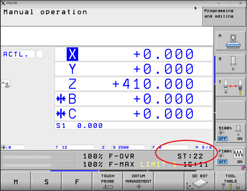
The iTNC 530 Manual Operation screen. At the bottom status bar, ST shows the current part count — the value circled here (ST:22) means 22 parts have been completed. MachineMetrics reads this counter to track production. When connected and data is flowing, verify the part count in MachineMetrics Diagnostics matches the ST value visible on the control.
Step 3: Verify in Machine View
- Navigate to Machines → Select your Heidenhain machine
- Verify machine status displays correctly:
- Status (In Cycle, Idle, etc.)
- Current program
- Spindle speed
- Tool information
Part Counting Configuration
💡 Note for TNC 640 / TNC 730: If you're using OPC-UA Option 56, part counting is much easier and typically works automatically without manual PLC WORD configuration. The instructions below are primarily for machines using Option 18 or the proprietary Heidenhain connector.
Understanding PLC WORD Table
Heidenhain machines often do not have a dedicated, standard part counter location that MachineMetrics can read directly. Instead, part count data is typically stored in the PLC WORD table, which is a memory area within the control that stores various machine variables.
What is the PLC WORD Table?
The PLC WORD table is a data structure in the Heidenhain control that contains:
- Machine status flags
- Counters (including part counts)
- Process variables
- Custom user data
Why Different Locations?
Part counter addresses vary by:
- Control model (iTNC 530 vs TNC 640)
- Machine builder customization
- Auxiliary equipment (pallet changers, multi-spindle setups)
- Custom macros or programs
Finding Part Counter Location
To identify where the part counter is stored in the PLC WORD table, access the PLC diagnostic menu through the following steps. This procedure applies to the iTNC 530 / TNC 530.
Step 1: Select Programming and Editing mode
Press the Programming and Editing operating mode softkey (the right-arrow icon at the top-right of the softkey panel).
Step 2: Press the MOD key
Press the MOD key on the control's physical keyboard.
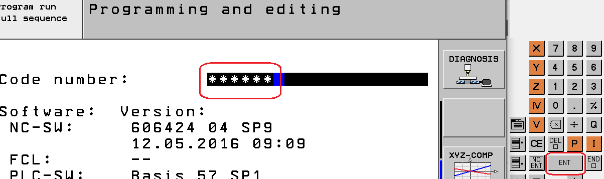
Step 3: Enter the access code
When the Code number: prompt appears, type 807667 then press ENT.
Note: If 807667 does not work, the machine builder may have set a custom PLC password — contact the machine builder for the correct code.
Step 4: Open the TABLE view
Use the arrow softkeys (◄ ►) to scroll the softkey bar until TABLE appears, then press TABLE.

Step 5: Switch to WORD view and DECIMAL mode
In the table view, press W (WORD) to show WORD-size values, then toggle HEX ↕ DEZIMAL to switch to decimal display. This makes it easier to match values with the machine's part counter readout.

Step 6: Locate the part counter in the WORD table
Scan the WORD table for a value that increments when a part completes. On most iTNC 530 machines the part counter is at W20, labeled WG_WERKSTUECK_ZAEHLER (German for "workpiece counter") in the status bar at the bottom of the screen when that cell is selected.
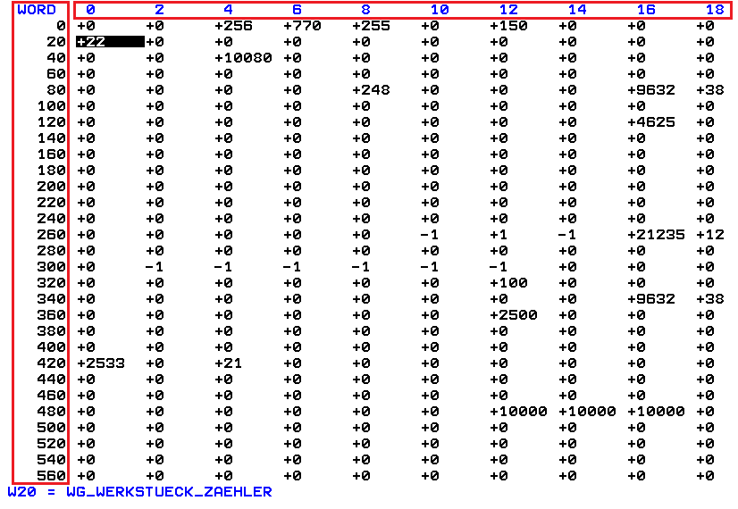
W20 = WG_WERKSTUECK_ZAEHLER is the most common part counter location on the iTNC 530. Run a cycle and watch the value at W20 increment to confirm.
Step 2: Search for Part Counter Terms
Look for labels containing the following terms (in English or German):
English Terms:
workorworkpiecepiece counterorpart counterparts madeorparts countcounterorcountproduction counter
German Terms:
werkstück zähler(workpiece counter)teilezähler(parts counter)arbeitszähler(work counter)zähler(counter)stückzahl(piece count)
Step 3: Note the WORD Address
Once you locate the part counter:
- Note the WORD address number (e.g., WORD 20, WORD 10, WORD 19944)
- Verify the value increments when parts are completed
- Document this address for MachineMetrics configuration
Common Part Counter Locations:
| Control Type | Typical Address | Notes |
|---|---|---|
| iTNC 530 | WORD 20 | Most common default location |
| TNC 640 | WORD 10 or WORD 19944 | Varies by machine builder |
| With Pallet Changer | Custom location | Often non-standard address |
| Multi-Spindle | Multiple addresses | Separate counter per spindle |
If Part Counter Not Found:
If you cannot locate a part counter in the PLC WORD table:
- Check machine documentation from manufacturer
- Contact machine builder for PLC WORD map
- Ask machine operator if custom macros track parts
- Consider implementing M-code based counting (see below)
Configuring Part Count Address
Once you've identified the PLC WORD address for the part counter, configure it in MachineMetrics.
Step 1: Add Part Counting Configuration
In the MachineMetrics machine configuration, add the part counting JSON configuration:
For iTNC 530 / TNC 530 (WORD 20):
{
  "partcounting": {
    "plcPartCountMemAddressTNC640": "20"
  }
}
For TNC 640 / TNC 730 (WORD 10):
{
  "partcounting": {
    "plcPartCountMemAddressTNC640": "10"
  }
}
For TNC 640 / TNC 730 (WORD 19944 - Alternative):
{
  "partcounting": {
    "plcPartCountMemAddressTNC640": "19944"
  }
}
Note: Despite the parameter name referencing "TNC640", this configuration works for all Heidenhain controls (iTNC 530, TNC 530, TNC 640, TNC 730). Simply change the address value to match your control's part counter location.
Step 2: Configure Data Mapping
- Go to Machine Settings → Data Mapping tab
- Locate the
part_countdata item - Map it to:
- Type: EVENT
- Subtype: PART_COUNT
- Component: Machine or Controller
- Click Save
Step 3: Configure Data Rules
- Go to Machine Settings → Data Rules tab
- Locate Part Counting section
- Set Part Count Source to
part_count - Configure reset behavior:
- Reset on Program Start: Optional (depends on your process)
- Reset on Shift: Optional
- Click Save
Verifying Part Count
Step 1: Run a Test Part
- Load a program on the machine
- Run the program to completion
- Verify part counter increments on the control display
Step 2: Check MachineMetrics Data
- Go to machine page in MachineMetrics
- Navigate to Parts tab
- Verify part count matches control display
- Check that timestamp is accurate
Step 3: Check Diagnostics
- Go to Diagnostics tab
- Locate
part_countdata item - Verify value updates when part completes
- Check for consistent updates (no missed counts)
Step 4: Monitor Over Time
- Run multiple parts
- Verify count increments correctly
- Check for reset behavior (if configured)
- Confirm data is flowing to MachineMetrics Cloud
Troubleshooting Part Count Issues:
If parts are not counting correctly:
- Verify PLC WORD address is correct (double-check on control)
- Check M-code execution (review program for M53/M54)
- Verify Data Mapping settings in MachineMetrics
- Check adapter logs for errors or warnings
- Confirm part counter is enabled on the control
- Test manual increment on control (if possible)
Troubleshooting
Connection Issues
Problem: Cannot Connect to Control
Possible causes:
- Incorrect IP address
- Network connectivity issue
- Firewall blocking communication
- No connectivity option installed (TNC 640/730 requires Option 56 or Option 18)
- Control not powered on or Ethernet disabled
Solutions:
- Verify IP address is correct and control is reachable (ping test)
- Check physical Ethernet cable connection
- Verify connectivity option is installed:
- TNC 640/730: Requires Option 56 (recommended) or Option 18
- Check SIK page to confirm option is active
- Check network settings on control (IP, subnet mask, gateway)
- Verify firewall rules allow port 19090 communication
- Restart control and Edge device
Problem: Intermittent Connection
Possible causes:
- Network instability
- DHCP IP address changing
- Control restarting during production
- High network traffic or latency
Solutions:
- Use static IP address instead of DHCP
- Check network switch/router for errors
- Verify network cable quality (replace if old/damaged)
- Monitor network latency with continuous ping
- Check for IP conflicts on network
Data Collection Issues
Problem: No Data Items Populating
Possible causes:
- Adapter configuration incorrect
- Control not exposing data
- Polling interval too high
- Data mapping not configured
Solutions:
- Review adapter configuration for typos or errors
- Verify control type matches configuration (TNC530 vs TNC640)
- Check Data Mapping settings in MachineMetrics
- Review adapter logs for specific errors
- Reduce poll_interval to 1000ms (1 second)
Problem: Specific Data Items Missing
Possible causes:
- Control does not support specific data type
- Data item not configured in adapter
- PLC data not exposed
Solutions:
- Verify control model supports requested data
- Check adapter configuration includes all desired data items
- Review Heidenhain control capabilities documentation
- Contact MachineMetrics support for control-specific limitations
Part Counting Issues
Problem: Part Count Not Incrementing
Possible causes:
- Incorrect PLC WORD address
- Part counter disabled on control
- M-code not executing
- Data mapping not configured
Solutions:
- Verify PLC WORD address is correct (check on control)
- Ensure part counter is enabled in control settings
- Check CNC program includes M53 (or appropriate M-code)
- Verify Data Mapping and Data Rules are configured
- Review adapter logs for part count events
- Test manual increment on control
Problem: Part Count Incorrect or Resetting Unexpectedly
Possible causes:
- Reading wrong PLC WORD address
- Multiple counters in use (pallet changer, etc.)
- Data Rules reset behavior misconfigured
- Control resetting counter on program start
Solutions:
- Verify correct PLC WORD address with machine documentation
- Check for multiple part counters (select appropriate one)
- Review Data Rules reset configuration
- Disable automatic reset if not desired
- Consult machine operator on expected behavior
Problem: Cannot Find Part Counter in PLC WORD Table
Possible causes:
- Part counter stored in different location
- Custom machine configuration
- No native part counter implemented
Solutions:
- Review complete PLC WORD table for any counter-like variables
- Contact machine builder for PLC WORD documentation
- Check for M-code based counting instead (M53/M54)
- Consider implementing custom macro for part counting
- Contact MachineMetrics support for alternative methods
Network Configuration Issues
Problem: Control Not Obtaining IP Address (DHCP)
Possible causes:
- DHCP server not responding
- Network cable issue
- Control Ethernet settings incorrect
Solutions:
- Check physical cable connection
- Verify DHCP server is functioning (check other devices)
- Try static IP configuration instead
- Restart control and network switch
- Check control Ethernet settings are set to DHCP/Automatic
Problem: Cannot Ping Control from Edge Device
Possible causes:
- Different subnets
- Firewall blocking ICMP
- Incorrect IP configuration
- Network routing issue
Solutions:
- Verify Edge and control are on same subnet
- Check firewall settings (disable temporarily to test)
- Verify IP address, subnet mask, and gateway settings
- Test with another device on same network
- Check network switch configuration
Additional Resources
MachineMetrics Resources:
- Machine Settings Guide - Configure machine settings and data mapping
- Connectivity Overview - Compare connectivity methods
- Network Requirements - Firewall and network configuration
Heidenhain Resources:
- HEIDENHAIN OPC UA NC Server - Product page for Option 56 (OPC-UA connectivity)
- HEIDENHAIN OPC UA Information Model — download the current Information Model PDF for Table 2 (Core Information Model vs. minimum NC software) and node definitions
- Heidenhain TNC User Manual (consult your specific control model)
- Heidenhain PLC Programming Manual
- Machine builder documentation (Hermle, DMG Mori, etc.)
Related Guides:
- OPC-UA Connectivity Guide — add OPC-UA machines, security, and adapter scripts in MachineMetrics
- Edge Device Setup - Configure MachineMetrics Edge
- Transform Adapter Scripts - Advanced data transformation
Getting Help
MachineMetrics Support:
- Email: support@machinemetrics.com
- Phone: 844-822-0664
Saving a Service File from the Control
When contacting support, Heidenhain (or MachineMetrics support) may ask for a service file — a ZIP archive exported directly from the control that contains NC programs, tool data, PLC state, and logs. The symbol.lst file inside the archive is particularly useful for identifying PLC WORD addresses on your specific machine.
Step 1: Press the ERR key
Press the ERR key on the physical keyboard to open the error/log menu.

Step 2: Press LOG FILES

Step 3: Press SAVE SERVICE FILES

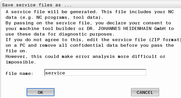
Step 4: Confirm and save
A dialog will appear. Confirm the filename (default: service) and press OK.
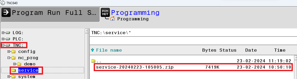
Step 5: Locate the ZIP file
Navigate to PGM MGT → TNC:\service\. The service ZIP file (e.g., service-20240223-105005.zip) will appear in this folder.
Step 6: Copy the file to a USB drive
Select the ZIP file, press the COPY softkey, then use the folder-browse softkey to select your USB drive as the destination.

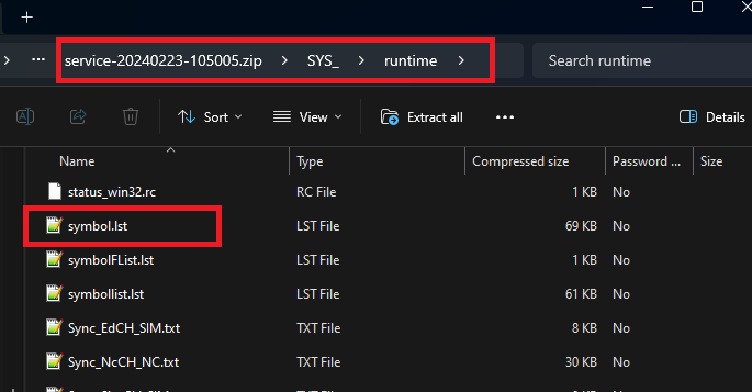
Step 7: Extract and locate symbol.lst
On your PC, extract the ZIP. Inside the SYS_\runtime\ path you will find symbol.lst — this file maps every PLC memory address to its label (e.g., WG_WERKSTUECK_ZAEHLER). Share this file with support to quickly identify the correct part counter address for your machine.
Before Contacting Support:
- Note the Heidenhain control type and model (iTNC 530, TNC 640, or TNC 730)
- Verify connectivity option is installed:
- TNC 640/730: Check for Option 56 (recommended) or Option 18
- iTNC 530: No option required
- Document IP address and network configuration
- Note PLC WORD address used for part counting (if applicable)
- Capture screenshots of configuration screens
- Document any error messages from control or MachineMetrics
Information to Provide:
- Machine make, model, and control type (iTNC 530 or TNC 640)
- Network configuration (IP address, subnet, gateway)
- PLC WORD address for part counter (if known)
- Adapter configuration (YAML)
- Description of issue and troubleshooting steps already taken
- Screenshots of error messages or configuration screens
For Part Counting Issues:
- Provide PLC WORD table screenshot showing counter location
- Note M-codes used in programs (if applicable)
- Describe expected vs actual part counting behavior
- Include machine builder name (Hermle, DMG Mori, etc.)