Digital I/O
Digital I/O & Modbus TCP Connectivity Guide
- Overview
- Current I/O Hardware
- Retired Hardware
- Understanding Current Transducers
- Signal Selection Strategy
- Sealevel eI/O-170 Installation
- WISE-4050 Installation & Configuration
- Modbus TCP Addressing
- Comprehensive Adapter Script Examples
- Brother CNC I/O Integration
- Machine-Specific Integrations
- Troubleshooting
- Best Practices
- Additional Resources
- Getting Help
Adding a Digital I/O (Sealevel, WISE, etc.) machine in MachineMetrics configures the path to your I/O hardware over Modbus/TCP; it does not automatically map inputs, coils, and registers to utilization, part count, and other MachineMetrics data items. You must add a Transform Adapter Script that interprets your wired signals. Without it, the hardware may be reachable but no meaningful production data will appear — a common reason customers believe the integration failed.
Signal-to-data-item mapping is mandatory. See Comprehensive Adapter Script Examples on this page for full sample scripts and patterns. Contact support@machinemetrics.com if you need more help.
Overview
What is I/O Connectivity?
I/O (Input/Output) connectivity is used when we need to connect machines that do not have Ethernet or a communication protocol available. This is typically our approach for older machines that predate modern networked controls.
How It Works:
MachineMetrics uses a piece of hardware (typically a Sealevel or WISE device) installed in the machine's electrical cabinet. This hardware module connects to electrical signals from the machine to monitor activity and production.
Our Standard Approach:
- Utilization Signal (Machine Activity):
- Install a current transducer (CT) on a cable drawing current
- Typically attached to the spindle motor cable
- Detects when the machine is running vs. idle by monitoring motor current
- Part Count Signal:
- Capture a signal that indicates when a part is complete
- Lathes: Often use bar feed signal
- Mills: Often use fixture clamp signal or pallet changer
- Other machines: Part eject, part counter relay, etc.
The hardware module reads these electrical signals and sends the data to MachineMetrics over your network using Modbus TCP protocol.
When to Use I/O
Use I/O connectivity when:
- Machine does not support modern protocols (FOCAS, MTConnect, OPC-UA)
- Older legacy equipment (pre-2000 machines)
- Simple machine tools without networked controls
- Non-CNC machines (press brakes, injection molding, grinders, assembly equipment)
- Equipment with accessible electrical signals but no data interface
Key Technical Concepts
Understanding these terms will help as you configure I/O connectivity:
- Wet Contact: Signal provides its own voltage source (e.g., 24VDC output from PLC)
- Dry Contact: Simple switch closure, requires external voltage source
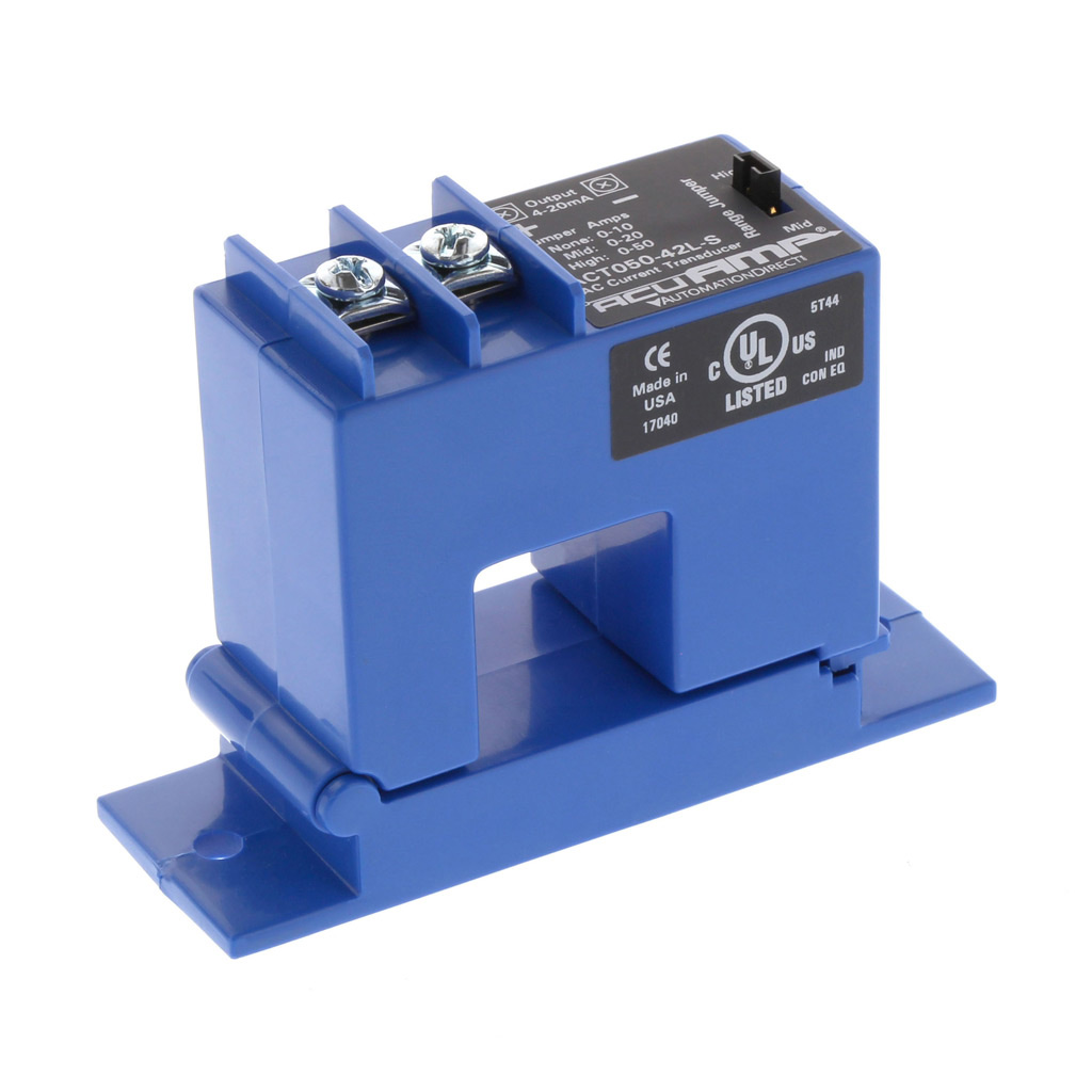
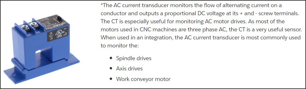
- Current Transducer (CT): Sensor that outputs proportional voltage or current based on AC motor current
- Optically Isolated: Electrical isolation between input and system ground (3000VDC+ typical)
- Modbus TCP: Industry-standard digital protocol for reading/writing data over Ethernet
Current I/O Hardware
Sealevel eI/O-170E / eI/O-170PoE
MachineMetrics' exclusive I/O solution for all new installations. We sell and support only this model.
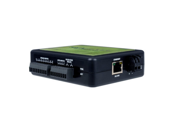
Sealevel eI/O-170 Ethernet I/O Module - A compact DIN-rail mounted device with digital inputs and outputs for connecting to machine signals. This module communicates via Modbus TCP and is commonly used for monitoring machine utilization through current transducers and capturing part counts from machine signals.
Specifications
Analog Inputs (8 channels):
- Voltage Ranges: 0-5V, 0-10V, ±5V, ±10V (software configurable)
- Resolution: 12-bit (4096 counts, 0.00244V per count at 10V range)
- Input Impedance: 100kΩ
- Channels: 8 single-ended OR 4 differential
- Typical Use: Current transducers (analog 0-10V CT models)
Digital Inputs (2 channels - Opto 1 & Opto 2):
- Type: Dry contact sensing (internally powered)
- Isolation: 1000VDC optical isolation
- Source Current: 12mA max
- Wiring: Connect switch/contact between input and common terminal
- ⚠️ CRITICAL: These inputs SOURCE current. DO NOT apply external voltage.
Power Options
Standard Model (eI/O-170E):
- Power: 9-30VDC, 3W typical
- Screw terminals on side of unit
- Use 24VDC shop power
Power over Ethernet (eI/O-170PoE):
- IEEE 802.3af-2003 PoE (Class 0)
- No separate power supply needed
- Single cable for power and data
- Requires PoE switch or injector
Physical Specifications
- Size: 4.5" L × 3.5" W × 1.3" H
- Mounting: DIN rail clip included (35mm rail)
- Terminals: 3.5mm removable screw terminals
- Status LEDs:
- Power (Green): Lights when powered
- Act (Green): Blinks during Modbus TCP activity
- Operating Temp: -40°C to 70°C
Purchasing
- Order from: shop.machinemetrics.com
- MachineMetrics provides pre-configured units
- Full technical support included
Advantech WISE-4050
Preferred wireless I/O solution that customers source directly from Advantech or distributors.
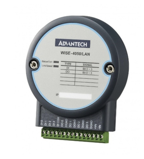
Advantech WISE-4050/LAN Ethernet I/O Module - Wired version with 4 digital inputs. The module features terminal connections for easy wiring and supports Modbus TCP communication. This is the LAN (wired Ethernet) variant; a wireless WiFi version (WISE-4050) is also available.
Specifications
Model: WISE-4050 (Wireless) or WISE-4050/LAN (Wired Ethernet)
Digital Inputs (4 channels):
- Type: Optically isolated
- Voltage Range: 10-50VDC
- Isolation: 3000VDC (optical)
- Wet Contact Compatible: Yes (10-50VDC)
- Dry Contact Compatible: Yes (requires external power)
Wireless Specifications (WISE-4050)
WiFi:
- Standard: IEEE 802.11 b/g/n
- Frequency: 2.4 GHz
- Range: Up to 150m (line of sight)
- Security: WEP, WPA, WPA2-PSK
- Modes: Infrastructure or AP mode
Network Configuration
Default Settings:
- Wireless AP Mode: SSID "WISE-4050-XXXXXX" (last 6 of MAC)
- Default IP: 192.168.1.1 (AP mode) or DHCP (Infrastructure mode)
- Default Login: root / 00000000 (8 zeros)
- Modbus Port: 502
- Web Interface: http://[IP-address]
Sourcing WISE-4050
Purchase Options:
- Direct from Advantech: www.advantech.com
- Distributors: DigiKey, Mouser, Newark, Arrow
- Typical Price: $150-250 USD
Part Numbers:
- WISE-4050: Wireless version
- WISE-4050/LAN: Wired Ethernet version
Additional Items Required for Wireless WISE-4050:
- Antenna extension cable (customer must purchase)
- Type: RP-SMA or compatible with WISE-4050 antenna connector
- Length: 1-3 feet recommended
- Features: Look for cables with magnetic base antenna for easy mounting
- Connects module inside cabinet to antenna outside cabinet
- Installation requirement: Hole must be drilled in electrical cabinet for external antenna mounting
Note: Wireless WISE-4050 requires antenna to be mounted externally to the electrical cabinet for proper WiFi signal reception. See Installation section for details.
Retired Hardware
LabJack T4/T7 (Hardwired)
⚠️ RETIRED: No longer sold by MachineMetrics. Existing installations fully supported.
If you already have these modules, they will continue to work with full MachineMetrics support. Analog voltage-based (0-40VDC) configuration.
LabJack U3 (Wireless)
⚠️ RETIRED: No longer sold by MachineMetrics. Existing installations fully supported.
Use Advantech WISE-4050 for new wireless installations.
Understanding Current Transducers
Types of Current Transducers
There are two types of CTs for different applications:
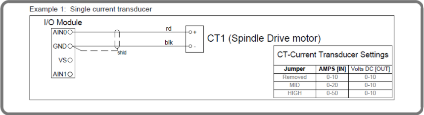
1. Analog Output CT (0-10VDC)
For use with Sealevel eI/O-170 Analog Inputs
Specifications:
- Input: 0-100A AC (or 0-200A for larger motors)
- Output: 0-10VDC (proportional analog voltage)
- Example: 50A motor current = 5VDC output
- Self-powered: No external power needed
Common Models:
- NK Technologies AT Series
- CR Magnetics CR5410
- Veris H Series
Wiring to eI/O-170:
CT (+) output → AN1 terminal
CT (-) output → AG terminal (analog ground)
Use Cases:
- Spindle motor monitoring (main utilization signal)
- Live tooling head monitoring
- Axis drive monitoring (Z-axis, etc.)
- Any motor-driven activity detection
2. Dry Contact Output CT (Switch Closure)
For use with Sealevel eI/O-170 Digital Inputs (Opto 1 & Opto 2)
Specifications:
- Input: 0-100A AC (adjustable setpoint)
- Output: Dry contact closure when current exceeds setpoint
- Requires: External voltage source for switch sensing
- Adjustable Trip Point: Set threshold for switch activation
Common Models:
- NK Technologies AS2 Series
- Veris H800 Series with switch output
Wiring to eI/O-170 Digital Input:
External 24VDC (+) → One side of CT switch output
Other side of CT switch → Opto 1 terminal
COM terminal → External 24VDC (-)
Use Cases:
- Simple on/off detection (machine running or not)
- When analog resolution not needed
- Cost-effective solution
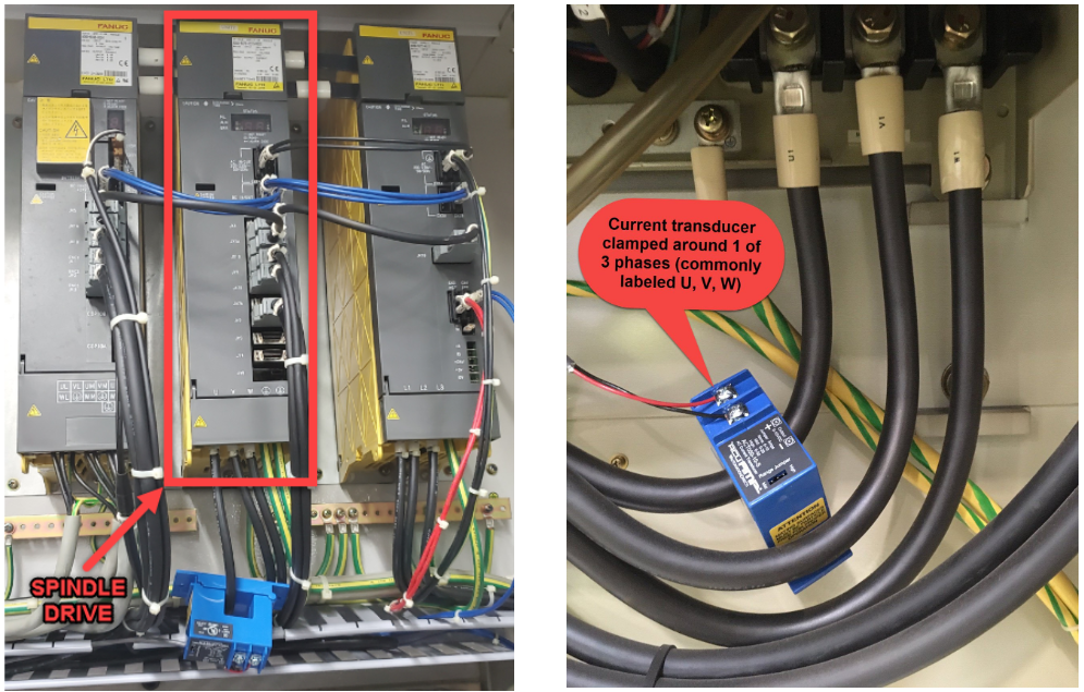
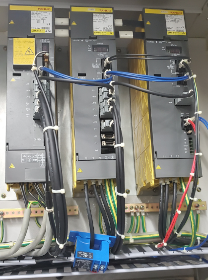
Installing a Current Transducer
Step 1: Identify Motor to Monitor
- Usually spindle motor drive
- Could be live tooling head
- Could be axis drive (Z-axis for lathes)
- For multi-spindle: CT on each spindle
Step 2: Access Motor Power Wires
- Open electrical cabinet
- Find motor drive or contactor
- Identify three phase wires (L1, L2, L3)
Step 3: Install CT
- Clamp CT around ONE phase wire only (any of the three)
- Arrow on CT should point toward motor
- Secure CT so it doesn't vibrate loose
- Do not clamp around multiple wires
- Do not clamp around insulated cable bundle (individual wire only)
Step 4: Wire CT Output
- Analog CT: Connect to AN1 and AG terminals
- Dry Contact CT: Connect through external 24VDC to Opto 1
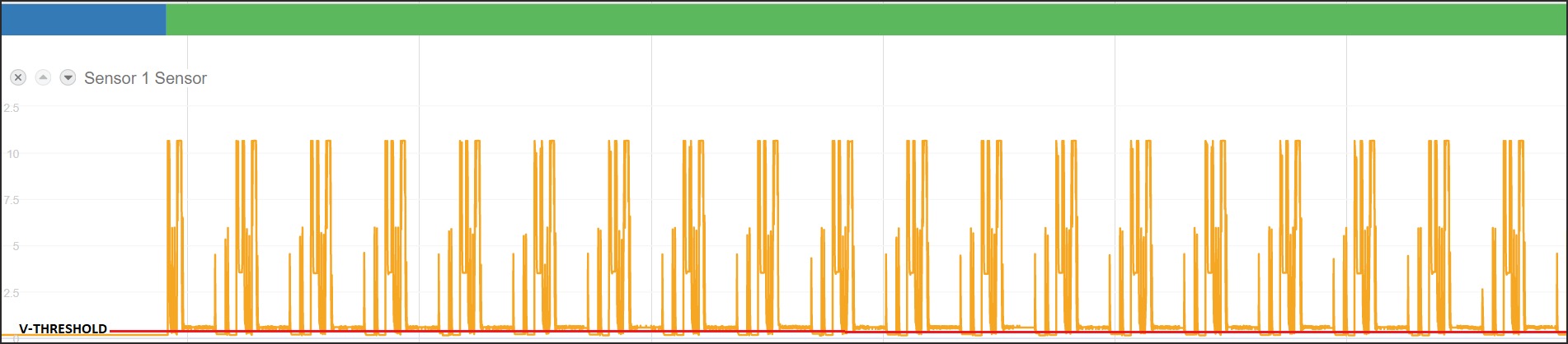
What good CT data looks like in MachineMetrics:
Signal Selection Strategy
Utilization Signals
Goal: Determine if machine is ACTIVE or IDLE.
Preferred Methods (in order):
-
Current Transducer on Spindle (Most Reliable)
- Analog CT: Monitors actual motor current
- Set low threshold (1.0-1.5V) for low-speed detection
- Works on almost any spindle-driven equipment
-
Green Stack Light (If Accurate)
- Wet contact: 24VDC when machine running
- Simple and reliable
- Verify it accurately reflects in-cycle state
Stack light output terminals are typically labeled on the CNC terminal block inside the electrical cabinet. Look for PATGC / PATG (green — running), PATYC / PATY (yellow — idle/alarm), and PATRC / PATR (red — alarm).
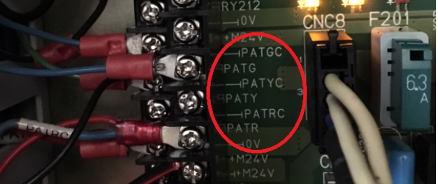
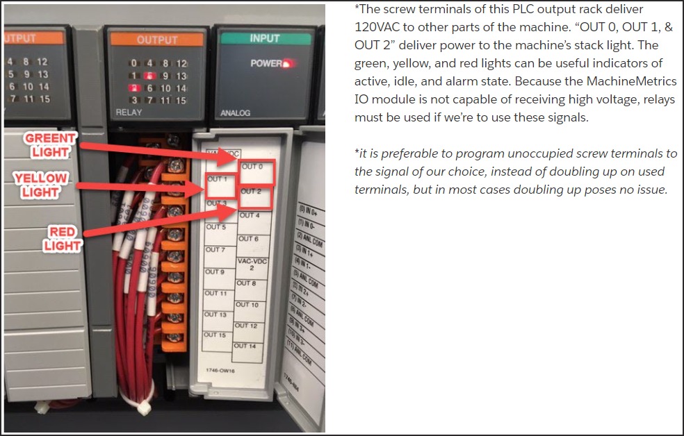
⚠️ Important: Many machines deliver 120VAC or 24VAC to stack light outputs — the MachineMetrics I/O module cannot receive high-voltage signals directly. If the PLC outputs high voltage, relays are required to step down or isolate the signal.
-
PLC Output "In Cycle" (If Available)
- Dedicated signal from PLC
- Most accurate when available
- May be labeled "Auto Mode", "Cycle Active", etc.
Part Count Signals
Goal: Detect when a part has been completed.
Preferred Methods (in order):
-
Part Count Relay (Ideal)
- Dedicated relay triggered by M-code in program
- Pulses briefly after each part
- Most reliable method
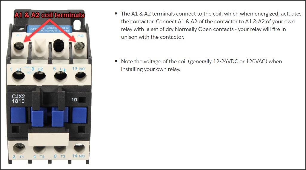
Many machining centers have spare M-code relays built in (e.g., M70/M71 on HMCs). You can also piggyback your own relay onto an existing contactor by wiring to the A1 & A2 coil terminals — your relay fires in unison with the machine's relay.
-
Pallet Changer Signal (Mills with Pallets)
- Signal when pallet changes
- Each pallet change = parts completed
- Monitor "Pallet Index Complete" or similar
-
Barfeeder Pulse (Lathes with Barfeeders)
- Signal when barfeeder advances
- Each advance = new part started
- May need logic: count on part eject, not bar advance
-
Part Ejector/Unloader
- Signal from part handling equipment
- Part catcher, conveyor, or robot
- May need combination logic (ejector AND auto mode)
-
Coolant Pump Pulse (Last Resort)
- ⚠️ Use only when other methods not available
- Requires two M-code pulses (on, off, on, off)
- Must use min-delta and max-delta for timing verification
- Can cause excessive coolant pump wear
- Requires program modifications
After wiring and configuring a part count signal, use the Connectivity Validation Guide to confirm the signal is behaving correctly — including how to spot bad counts on the Timeline before they affect production reporting.
Sealevel eI/O-170 Installation
Physical Installation
Step 1: Mount Module
- Install on 35mm DIN rail in electrical cabinet
- Keep away from high-voltage lines (>240VAC)
- Accessible location for wiring
- Protected from coolant and chips
Step 2: Power Connection
Standard Model (eI/O-170E):
24VDC (+) → V+ terminal (side of module)
24VDC (-) → V- terminal
PoE Model (eI/O-170PoE):
- Connect CAT5/CAT6 ethernet cable
- PoE provides power automatically via ethernet
Step 3: Network Connection
- Connect ethernet cable to RJ45 port
- Connect to network switch
- Module communicates with Edge device over network
Network Configuration
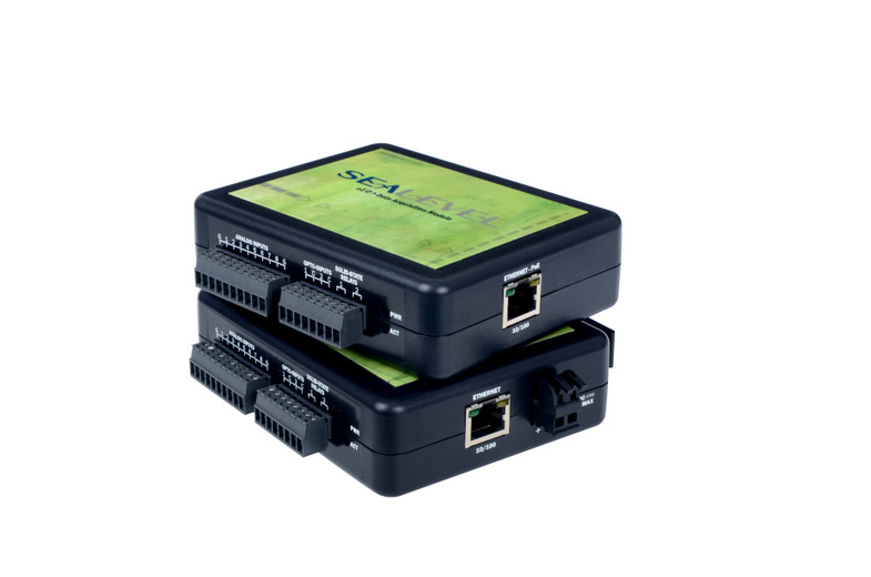
Sealevel I/O Module with terminal connections - The module features multiple digital input and output terminals for wiring machine signals. Note the clear terminal labeling and the RJ45 Ethernet port for network connectivity. This view shows the actual connection points where you'll wire current transducers, part count signals, and other machine I/O.
Step 1: Download SeaMAX Software
- Visit: https://www.sealevel.com/software-seamax-windows
- Download SeaMAX Suite for Windows
- Install as administrator
Step 2: Discover Module
- Launch "Ethernet Config" utility (Start → All Programs → Sealevel Systems → SeaMAX → Ethernet Configuration Tool)
- Click "Search for SeaI/O Devices"
- Modules on network will appear
- Default IP: 192.168.42.253
Step 3: Configure Static IP
- Select module in device list
- Enter new static IP address (from your IT team)
- Example: 192.168.1.101
- Enter subnet mask: 255.255.255.0
- Enter gateway (if required)
- Click "Apply Changes"
- Module will reboot with new IP
Step 4: Verify Connection
- Ping module from Edge device or computer
- Launch MaxSSD utility (Start → All Programs → Sealevel Systems → SeaMAX → MaxSSD Configuration Utility)
- Select "Ethernet" from COM Port dropdown
- Select module IP from list
- Click "Get SeaIO Module Settings"
- Module information should display
Terminal Wiring
Analog Inputs (for CTs):
AN1 - Analog Input 1 (address 0, e.g., main spindle CT)
AN2 - Analog Input 2 (address 1, e.g., live tooling CT)
AN3 - Analog Input 3 (address 2, e.g., Z-axis CT)
AN4 - Analog Input 4 (address 3)
AN5 - Analog Input 5 (address 4)
AN6 - Analog Input 6 (address 5)
AN7 - Analog Input 7 (address 6)
AN8 - Analog Input 8 (address 7)
AG  - Analog Ground (common for all analog inputs)
Digital Inputs (Opto 1 & Opto 2):
Opto 1 - Digital Input 0 (dry contact sensing)
Opto 2 - Digital Input 1 (dry contact sensing)
COM    - Common for digital inputs
⚠️ CRITICAL: Digital inputs are internally powered (source 12mA). Connect switch/relay contacts between Opto terminal and COM. DO NOT apply external voltage to these inputs.
Example: Dry Contact Relay Wiring to Opto 1:
External 24VDC (+) → One side of relay N.O. contact
Other side of relay contact → Opto 1 terminal
COM terminal → External 24VDC (-)
WISE-4050 Installation & Configuration
Advantech WISE-4050/LAN Ethernet I/O Module - A versatile wireless/wired I/O module with multiple digital inputs and outputs. This compact module supports both WiFi (WISE-4050) and Ethernet (WISE-4050/LAN) connectivity, making it ideal for machines where running cables is difficult. The module communicates via Modbus TCP and features indicator LEDs for easy status monitoring. Image shows the wired LAN version.
Physical Installation
Step 1: Mount Module
- Snap onto 35mm DIN rail
- Mount inside electrical cabinet for protection
Step 2: Antenna Mounting (Wireless WISE-4050 Only)
IMPORTANT: For wireless WISE-4050 modules, the antenna must be mounted externally to the electrical cabinet for proper WiFi signal reception.
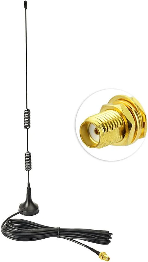
WiFi antenna extension cable with RP-SMA connector - Required for wireless WISE-4050 installations. The extension cable connects the WISE-4050 module inside the electrical cabinet to the antenna mounted outside the cabinet. The cable features spring-coiled sections for flexibility and a magnetic base antenna for easy external mounting.
Antenna Installation Requirements:
-
Drill Hole in Cabinet
- A hole must be drilled in the electrical cabinet wall
- Size: Appropriate for antenna connector/cable (typically 1/2" to 3/4")
- Location: Choose a location with clear line-of-sight to WiFi access points
- Coordinate with machine owner/electrician before drilling
-
Antenna Extension Cable Required
- Customer must purchase an antenna extension cable
- Cable connects WISE-4050 module (inside cabinet) to antenna (outside cabinet)
- Cable type: RP-SMA or compatible with WISE-4050 antenna connector
- Recommended length: 1-3 feet (minimize signal loss)
- Features: Magnetic base antenna for easy mounting
-
Mount Antenna Externally
- Route extension cable through drilled hole
- Attach antenna to outside of cabinet (magnetic base works well on metal cabinets)
- Secure antenna in position with appropriate mounting hardware
- Ensure antenna has clear path for WiFi signals
Note: The WISE-4050/LAN (wired Ethernet version) does not require antenna mounting. Simply connect an Ethernet cable to the module's RJ45 port.
Step 3: Power Connection
24VDC (+) → V+ terminal
24VDC (-) → V- terminal
DIP Switch Configuration
Before wiring signals to the WISE-4050, you must configure the DIP switches on the back of the module to set the input type (wet contact or dry contact) for each digital input channel.
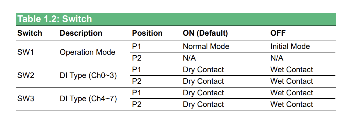
WISE-4050 DIP Switch Configuration - The module has three switches (SW1, SW2, SW3) on the back that control operation mode and input types. SW2 configures channels DI0-3, and SW3 configures channels DI4-7. Set to ON for dry contact or OFF for wet contact.
DIP Switch Functions:
| Switch | Description | Position | ON (Default) | OFF |
|---|---|---|---|---|
| SW1 | Operation Mode | P1 | Normal Mode | Initial Mode |
| P2 | N/A | N/A | ||
| SW2 | DI Type (Ch0-3) | P1 | Dry Contact | Wet Contact |
| P2 | Dry Contact | Wet Contact | ||
| SW3 | DI Type (Ch4-7) | P1 | Dry Contact | Wet Contact |
| P2 | Dry Contact | Wet Contact |
Understanding Contact Types:
Wet Contact (Switch OFF)
- Machine provides voltage on the signal wire
- Example: Machine outputs 24VDC when signal is active
- Common for: Stack lights, relay outputs, PLC outputs with power
- Wiring: Connect signal wire to DI terminal, no external power needed
Dry Contact (Switch ON - Default)
- Machine provides contact closure only (no voltage)
- Requires external power supply
- Common for: Relay contacts, switch contacts, mechanical contacts
- Wiring: Connect external 24VDC (+) to one side of contact, other side to DI terminal
Configuration Examples:
Example 1: All Wet Contacts (Stack Lights)
- Machine outputs 24VDC on all signals
- Set SW2 P1, P2 = OFF (channels DI0-3)
- Set SW3 P1, P2 = OFF (channels DI4-7)
Example 2: All Dry Contacts (Relay Contacts)
- Machine has relay contacts only
- Set SW2 P1, P2 = ON (channels DI0-3) - Default
- Set SW3 P1, P2 = ON (channels DI4-7) - Default
- Provide external 24VDC power
Example 3: Mixed Configuration
- DI0-3: Wet contacts (stack lights)
- DI4-7: Dry contacts (relay contacts)
- Set SW2 P1, P2 = OFF (wet contact for DI0-3)
- Set SW3 P1, P2 = ON (dry contact for DI4-7)
Important Notes:
⚠️ POWER OFF the WISE-4050 before changing DIP switch settings. Changing switches while powered can damage the module.
⚠️ MATCH SIGNAL TYPE to switch setting. Applying 24VDC to an input configured for dry contact can damage the module.
Step 4: Wire Signal Connections
After configuring DIP switches, wire your machine signals according to the contact type selected.
WiFi Configuration (Wireless Model)
Initial Setup - Connect to WISE AP:
- Power on WISE-4050
- Module creates its own WiFi network on first boot
- SSID:
WISE-4050-XXXXXX(last 6 digits of MAC address) - No password required initially
- Connect Computer to WISE WiFi
- Use laptop or tablet
- Connect to WISE-4050-XXXXXX WiFi network
- Computer will receive IP via DHCP
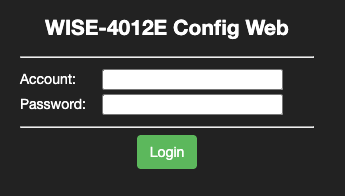
- Access Web Interface
- Open web browser
- Navigate to:
http://192.168.1.1 - Login:
root - Password:
00000000(8 zeros)
If unsuccessful, check the IP address printed on the back of the device.
Configure for Your Shop WiFi (Infrastructure Mode):
- Change to Infrastructure Mode
- In web interface, go to: Network → WLAN → Mode
- Select: Infrastructure
- Click Submit
- Select Your WiFi Network
- Go to: Network → WLAN → Infrastructure Settings
- SSID: Enter your shop WiFi network name
- Security: Select security type (WPA2-PSK recommended)
- Password: Enter your WiFi password
- Click Submit
- Configure Static IP (Recommended)
- Go to: Network → LAN → Ethernet/WLAN IP Configuration
- Uncheck Enable DHCP
- IP Address: Enter static IP (from IT team)
- Example: 192.168.1.150
- Subnet Mask: 255.255.255.0
- Gateway: Your network gateway
- Click Submit
- Set Modbus Unit ID
- Go to: I/O Status → Modbus Address
- Unit ID: Set to
1(or as required) - Click Submit
- Reboot Module
- Go to: Maintenance → System → Reboot
- Click Reboot
- Module will restart and connect to your WiFi
- Verify Connection
- Reconnect computer to your shop WiFi
- Navigate to new IP address:
http://192.168.1.150(your configured IP) - Should see WISE web interface
- Verify WiFi signal strength in web interface
Important Security Settings:
- Change Default Password
- Go to: Maintenance → Account
- Change password from default
00000000 - Use strong password
- Document password for future access
WISE-4050/LAN Configuration (Wired Model)
- Connect ethernet cable to RJ45 port
- Access web interface at default IP:
http://192.168.1.1 - Login: root / 00000000
- Configure static IP as described above
- Set Modbus Unit ID to 1
Terminal Wiring Examples
IMPORTANT: Ensure DIP switches are configured correctly BEFORE wiring signals. See DIP Switch Configuration section above.
Wet Contact Wiring (DIP Switch OFF)
Use when machine provides voltage on signal wire (e.g., stack lights, PLC outputs with power):
Green Light (+24VDC) → DI0+ terminal
Green Light (0V/GND) → COM terminal

Yellow Light (+24VDC) → DI1+ terminal
Yellow Light (0V/GND) → COM terminal

Part Signal (+24VDC) → DI2+ terminal
Part Signal (0V/GND) → COM terminal
DIP Switch Setting: SW2 OFF (for DI0-3)
Dry Contact Wiring (DIP Switch ON - Default)
Use when machine provides contact closure only (e.g., relay contacts, mechanical switches):
External 24VDC (+) → DI0+ terminal
Relay Contact (NO) → DI0- terminal
Relay Contact (COM) → COM terminal

External 24VDC (+) → DI1+ terminal
Switch Contact → DI1- terminal
Switch Contact → COM terminal
DIP Switch Setting: SW2 ON (for DI0-3) - This is the default setting
Mixed Contact Example
DI0-3 configured for wet contacts (stack lights):
DIP Switch SW2: OFF
Green Light (24VDC) → DI0+
Yellow Light (24VDC) → DI1+
Red Light (24VDC) → DI2+
All grounds → COM
DI4-7 configured for dry contacts (relay):
DIP Switch SW3: ON (default)
External 24VDC (+) → DI4+
Relay contact → Between DI4- and COM
WISE High-Frequency Counter Mode (Advanced)
For applications requiring RPM tracking or high-frequency pulse counting (e.g., conveyor speed, encoder pulses, production counters), we recommend using a WISE unit (either wireless or wired) configured in counter mode.
When to Use Counter Mode
Common use cases:
- RPM monitoring: Spindle speed from encoder pulses
- Conveyor speed: Tracking belt or chain speed from proximity sensors
- High-speed part counting: Fast production lines with high pulse rates
- Encoder tracking: Position or speed from rotary encoders
- Frequency measurement: Any signal above 10 Hz
Why WISE for High-Frequency?
- Standard digital inputs sample too slowly for fast pulses
- Counter mode accumulates pulses in hardware (no missed counts)
- Can handle frequencies up to several kHz
- Polling adapter reads total count, not individual pulses
Configuring WISE Input as Counter
Step 1: Access WISE Web Interface
- Navigate to WISE IP address in browser:
http://192.168.1.150(your configured IP) - Login:
root/ your password - Go to: I/O Status → Digital Input Configuration
Step 2: Set Input Mode to Counter
- Select the input channel (DI0, DI1, DI2, or DI3)
- Mode: Change from "Digital Input" to "Counter"
- Counter Type: Select "Frequency Counter" or "Pulse Counter"
- Click Submit and Reboot the module
Note: Once an input is set to counter mode, it accumulates pulses continuously. The adapter script reads the current count value and calculates the difference since the last reading.
How Counter Mode Works
Normal Digital Input Mode:
- Adapter reads:
trueorfalse(on/off state) - High-speed pulses may be missed between reads
- Limited to ~10 Hz sampling frequency
Counter Mode:
- Adapter reads: Current accumulated count (integer)
- WISE hardware counts every pulse (no missed counts)
- Adapter calculates:
count_difference = current_count - previous_count - Supports frequencies up to several kHz
Polling Frequency:
- Use
resampleparameter in variables for precise sampling control - For RPM:
resample: 5(5-second sampling) is usually sufficient - For real-time counting: Use
resample: 0.5orresample: 1(500ms or 1-second sampling) - More accurate and reliable than global
scan-interval
Recommended: Place
resamplein the variable pipeline (e.g., aftervalue-increase-diff) for best results.
WISE Counter Register Addresses
When using counter mode, WISE modules expose counter values as Modbus holding registers. Use raw PDU addressing with an explicit func: 3:
| Digital Input | Address (PDU) | Function Code | Type |
|---|---|---|---|
| DI0 | 0 | 3 (Read Holding Registers) | uint16 |
| DI1 | 1 | 3 | uint16 |
| DI2 | 2 | 3 | uint16 |
| DI3 | 3 | 3 | uint16 |
Important: Counter mode changes the input from a boolean coil to a 16-bit register. The digital input coil remains available separately for reading the current state.
address: 0 and not address: 40001?Modbus has two ways to refer to the same register:
| Style | Example | How it works |
|---|---|---|
| 5-digit convention | address: 40001 | The leading 4 implies FC3; remaining digits minus 1 = PDU register |
| Raw PDU addressing | address: 0, func: 3 | Direct 0-based register number; function code declared explicitly |
Both address: 40001 and address: 0, func: 3 point to the exact same physical holding register. For WISE counter registers, raw PDU addressing is required — the DI0 counter lives at PDU register 0 (not 40019). Trying address: 40019 points to PDU register 18, which is a completely different register.
When you use a raw address like 0, the script cannot infer the function code from the number alone, so you must explicitly include func: 3.
Simple Example: Basic Part Counter (WISE DI0)
This is the minimal working configuration for a WISE device counting parts via a high-frequency counter on DI0. This script uses a fast scan-interval and derives execution state from counter activity.
Hardware Setup:
- WISE-4050 or WISE-4050/LAN
- DI0: Part count pulse signal (configured as counter in WISE web interface)
Configuration:
version: 2
unit-id: 1
scan-interval: 0.25

registers:
  part-count:
    address: 0 # DI0 counter register
    func: 3
    type: uint16

variables:
  counter-changed:
    - source: part-count
    - value-increase

  execution:
    - source: counter-changed
    - off-delay: 10 # hold on the run signal for 10s
    - state:
        - ACTIVE: this
        - READY: true

data-items:
  - execution
  - part-count
Key Points:
address: 0, func: 3reads the DI0 counter register using raw PDU addressingtype: uint16is correct for counters — values are always positive (0–65,535)scan-interval: 0.25polls the counter every 250ms (suitable for high-frequency signals)value-increasedetects when the counter goes up; used to drive execution stateoff-delay: 10keeps the machine in ACTIVE state for 10 seconds after the last pulse
Sample Script: RPM Calculation from Encoder
Hardware Setup:
- WISE-4050 or WISE-4050/LAN
- DI0: Encoder pulse output (configured as counter in WISE web interface)
- Encoder: 60 pulses per revolution (PPR)
- Resample interval: 5 seconds
Configuration:
version: 2
unit-id: 1

registers:
  encoder-count:
    address: 0 # DI0 counter register
    func: 3
    type: uint16

variables:
  # Track count increase (pulses since last reading)
  pulse-diff:
    - source: encoder-count
    - value-increase-diff # Returns difference from last reading
    - resample: 5 # Sample counter every 5 seconds

  # Calculate RPM from pulse difference
  # Formula: RPM = (pulses / PPR) * (60 / resample_interval)
  # With 60 PPR and 5-second resample: RPM = (pulses / 60) * (60 / 5)
  # Simplified: RPM = pulses / 5
  spindle-rpm:
    - source: pulse-diff / 5
    - expression: round(this, 0) # Round to whole number

  # Optional: Execution state from RPM
  execution:
    - source: spindle-rpm > 100 # Active if RPM > 100
    - state:
        - ACTIVE: this
        - READY: true

data-items:
  - spindle-rpm
  - encoder-count
  - execution
Key Points:
address: 0, func: 3reads the DI0 counter using raw PDU addressingtype: uint16is correct for counters (unsigned 0–65,535)resample: 5in the variable pipeline samples the counter value every 5 seconds- More accurate and reliable than using
scan-interval value-increase-diffreturns the count increase since last reading- RPM formula depends on PPR (pulses per revolution) and resample interval
- Roll-over is handled automatically by
value-increase-diff
Note: The
resampleparameter goes in the variables section, not on the register definition.
Sample Script: High-Speed Part Counting
Hardware Setup:
- WISE-4050
- DI1: Part sensor configured as counter in WISE web interface
- Part sensor pulses once per part
- Resample interval: 1 second
Configuration:
version: 2
unit-id: 1

registers:
  parts-counter:
    address: 1 # DI1 counter register
    func: 3
    type: uint16

variables:
  # Extract count difference and accumulate
  part-count:
    - source: parts-counter
    - value-increase-diff # Get new parts since last poll
    - resample: 1 # Sample counter every 1 second
    - count # Accumulate into total

  # Calculate parts per minute (production rate)
  parts-per-minute:
    - source: parts-counter
    - value-increase-diff
    - resample: 1 # Sample counter every 1 second
    - expression: this * 60 # Scale 1-second reading to per-minute

  # Execution based on production activity
  execution:
    - source: parts-per-minute > 5 # Active if producing
    - off-delay: 30 # Hold for 30 seconds
    - state:
        - ACTIVE: this
        - READY: true

data-items:
  - part-count
  - parts-per-minute
  - parts-counter
  - execution
Key Points:
- Counter mode ensures no pulses are missed on fast production lines
address: 1, func: 3reads the DI1 counter using raw PDU addressingtype: uint16is correct for counters (unsigned 0–65,535)resample: 1in the variable pipeline samples the counter value every 1 secondvalue-increase-diffgets new parts since last readingcountoperation accumulates differences into running total- Scale to per-minute by multiplying by
60 / resample_interval - Counter will roll over at 65,535 (handled automatically)
Note: The
resampleparameter goes in the variables section, not on the register definition.
RPM Calculation Reference
General RPM Formula:
RPM = (pulses_per_scan / pulses_per_revolution) * (60 / scan_interval_seconds)
Example Calculations:
| PPR | Scan Interval | Pulses Counted | RPM Calculation |
|---|---|---|---|
| 60 | 5 seconds | 300 | (300/60) * (60/5) = 60 RPM |
| 1 | 5 seconds | 50 | (50/1) * (60/5) = 600 RPM |
| 100 | 1 second | 50 | (50/100) * (60/1) = 30 RPM |
| 360 | 5 seconds | 1800 | (1800/360) * (60/5) = 60 RPM |
Simplified Formulas for Common Configurations:
# 60 PPR, 5-second resample:
pulse-diff:
  - source: encoder-count
  - value-increase-diff
  - resample: 5
spindle-rpm:
  - source: pulse-diff / 5

# 1 PPR (1 pulse per revolution), 5-second resample:
pulse-diff:
  - source: encoder-count
  - value-increase-diff
  - resample: 5
spindle-rpm:
  - source: pulse-diff * 12

# 100 PPR, 1-second resample:
pulse-diff:
  - source: encoder-count
  - value-increase-diff
  - resample: 1
spindle-rpm:
  - source: pulse-diff * 0.6

# 360 PPR, 5-second resample:
pulse-diff:
  - source: encoder-count
  - value-increase-diff
  - resample: 5
spindle-rpm:
  - source: pulse-diff / 30
Complete Working Example: WISE High-Frequency Counter
This is a real-world configuration using a WISE unit with DI0 configured as a counter.
Hardware Setup:
- WISE-4050 or WISE-4050/LAN
- DI0: High-frequency pulse input (configured as counter in WISE web interface)
- DI0 also used for execution state detection
Basic Counter Configuration:
version: 2
unit-id: 1

coils:
  di0:
    address: 0 # Digital input state (still available)
    func: 2 # Read Discrete Inputs

registers:
  counter1:
    address: 0 # DI0 counter register
    func: 3 # Read Holding Registers
    type: uint16

variables:
  execution:
    - source: di0 # Use digital input state
    - resample: 0.1 # Sample every 100ms for fast response
    - state:
        - ACTIVE: this
        - READY: true

data-items:
  - di0 # Current input state
  - execution # Derived state
  - counter1 # Counter value
With RPM Calculation:
version: 2
unit-id: 1

coils:
  di0:
    address: 0
    func: 2

registers:
  counter1:
    address: 0 # DI0 counter register
    func: 3
    type: uint16

variables:
  # Calculate pulses since last reading
  pulse-diff:
    - source: counter1
    - value-increase-diff
    - resample: 5 # Sample counter every 5 seconds

  # Calculate RPM (assuming 60 pulses per revolution)
  # Formula: (pulses / 60 PPR) * (60 seconds / 5 second resample)
  # Simplified: pulses / 5
  spindle-rpm:
    - source: pulse-diff / 5
    - expression: round(this, 0)

  # Execution from RPM threshold
  execution:
    - source: spindle-rpm > 100
    - state:
        - ACTIVE: this
        - READY: true

data-items:
  - di0
  - execution
  - counter1
  - spindle-rpm
Key Points:
address: 0, func: 3reads the DI0 counter using raw PDU addressingtype: uint16is correct — counter values are always positive (0–65,535)- Digital input coil (DI0 state) uses
address: 0, func: 2— same channel, different function code resamplein variables controls sampling frequency for each data point- Both the counter value and input state are output
Note: The
resampleparameter goes in the variables section, not on registers or at the global level.
Counter Roll-Over Handling
Since the counter is uint16, it will roll over at:
- Maximum: 65,535
- Rolls to: 0
The value-increase-diff operation handles this roll-over automatically, so your counts remain accurate even after roll-over occurs.
Troubleshooting Counter Mode
Counter not incrementing:
- Verify input is configured as counter in WISE web interface
- Check signal wiring and voltage (should be 10-50VDC for wet contact)
- Test signal with multimeter or oscilloscope
- Ensure signal frequency is within WISE specifications
Incorrect RPM or count:
- Verify PPR (pulses per revolution) for your encoder
- Check scan interval matches script configuration
- Confirm register address matches DI channel
- Test with known RPM source for calibration
Counter resets unexpectedly:
- Check WISE power supply stability
- Verify network connectivity (dropped connections can cause resets)
- Review WISE system logs in web interface
Adding the Device in MachineMetrics
Once your Sealevel or WISE module is physically installed and configured with a static IP, you can add it as a Data Collection Method in MachineMetrics.
Step 1: Open Data Collection Settings
Navigate to Assets → Machines → [Machine] → Settings → Data Collection and click + Add a new Data Collection Method.
Step 2: Select Integration Type
Choose the integration type that matches your hardware:
| Hardware | Integration Type to Select |
|---|---|
| Sealevel eI/O-170E / eI/O-170E-ROHS | Modbus |
| Advantech WISE-4050 / WISE-4050/LAN | Modbus |
| LabJack T4 | Digital IO (T4-Module) |
| Generic Modbus/TCP device | Modbus |
[digital-io-dropdown-1.png placeholder]
[digital-io-dropdown-2.png placeholder]
[digital-io-dropdown-3.png placeholder]
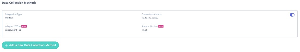
Step 3: Enter the Connection Address
The format of the Connection Address depends on which integration type you selected:
Modbus-based devices (Sealevel, WISE, Generic Modbus):
Enter both the IP address and the port number, separated by a colon:
[IP address]:[port]
Example:
10.20.112.52:502
Do not enter the IP address alone. If the port is missing, MachineMetrics cannot open a Modbus/TCP connection and the machine will show as offline.
- Standard Modbus port:
502(used by Sealevel and WISE modules unless changed) - To confirm the port: check the device's web interface or documentation
LabJack T4 (T4-Module):
The T4-Module integration uses an older method that does not use Modbus/TCP. Enter the IP address only — do not include a port number.
- ✅ Correct:
10.120.40.88 - ❌ Incorrect:
10.120.40.88:502
Including a port number will cause the connection to fail.
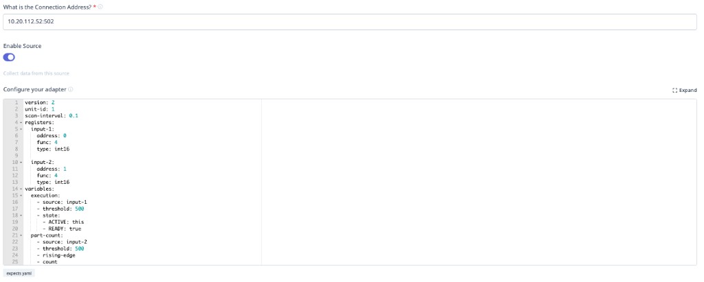
Step 4: Add an adapter script — mandatory before any data appears
The connection address routes network traffic to your I/O module. It does not tell MachineMetrics what the signals mean. You must paste a Transform Adapter Script into the "Configure your adapter" field below the connection address.
Without a script:
- The device may show as reachable
- No utilization, part count, or alarm data will appear
- This is the most common reason I/O integrations appear to fail
See Comprehensive Adapter Script Examples on this page for ready-to-use scripts for Sealevel and WISE modules.
Step 5: Save and verify
Click Save. The machine should connect within 30–60 seconds. Navigate to the machine timeline to confirm signals are being received.
Modbus TCP Addressing
Sealevel eI/O-170 Address Map
Analog Inputs:
- AN1 → Register 0 (function 4, type int16)
- AN2 → Register 1 (function 4, type int16)
- AN3 → Register 2 (function 4, type int16)
- AN4 → Register 3 (function 4, type int16)
- AN5 → Register 4 (function 4, type int16)
- AN6 → Register 5 (function 4, type int16)
- AN7 → Register 6 (function 4, type int16)
- AN8 → Register 7 (function 4, type int16)
Digital Inputs (Opto 1 & Opto 2):
- Opto 1 → Coil 0 (function 2 - Read Discrete Inputs)
- Opto 2 → Coil 1 (function 2 - Read Discrete Inputs)
WISE-4050 Address Map
Digital Inputs:
- DI0 → Coil 0 (function 2 - Read Discrete Inputs)
- DI1 → Coil 1 (function 2 - Read Discrete Inputs)
- DI2 → Coil 2 (function 2 - Read Discrete Inputs)
- DI3 → Coil 3 (function 2 - Read Discrete Inputs)
Data Types
Sealevel eI/O-170:
- Analog Inputs:
int16(0-4095 raw counts) - Digital Inputs: Boolean (coils)
WISE-4050:
- Digital Inputs: Boolean (coils)
Comprehensive Adapter Script Examples
Tip: Use Max — MachineMetrics’ AI assistant — to help generate or refine Digital I/O adapter scripts for your wired signals. The examples below are starting points.
Reference Documentation:
- Adapter Scripts Guide: https://developers.machinemetrics.com/docs/adapter-scripts/intro
- Available Operations: https://developers.machinemetrics.com/docs/adapter-scripts/operations
Example 1: CT for Execution (Main Spindle)
Hardware: Sealevel eI/O-170E
- AN1: Main spindle CT (analog 0-10V model)
Configuration:
version: 2
unit-id: 1

registers:
  spindle-raw:
    address: 0 # AN1
    func: 4 # Read Input Registers
    type: int16 # Raw ADC counts (0-4095)

variables:
  # Convert raw ADC counts to voltage (0-10V range)
  # 4096 counts = 10V, so divide by 409.6 to get voltage
  ct-voltage-int:
    - source: spindle-raw / 409.6 # Intermediate voltage (0.0 to 10.0 VDC)

  # Create cleaned version for data output (reduces noise/database load)
  ct-voltage:
    - source: ct-voltage-int
    - resample: 0.5 # Sample every 500ms
    - min-delta: 0.1 # Only report changes >0.1V

  # Execution based on voltage threshold with off-delay
  execution:
    - source: ct-voltage-int > 1.15 # 1.15V threshold
    - off-delay: 10 # 10 second off-delay (prevents flicker)
    - state:
        - ACTIVE: this
        - READY: true

data-items:
  - execution
  - ct-voltage # Send cleaned voltage value for trending
Key Points:
- Raw ADC is 0-4095 (12-bit)
- Divide by 409.6 to convert to 0-10V
- Create intermediate variable (
ct-voltage-int) for threshold logic - Create cleaned variable (
ct-voltage) with resample and min-delta for data output - Use cleaned version in
data-itemsto reduce database load - 1.15V threshold catches low-speed operations
- 10-second off-delay prevents flicker during rapid start/stop
Example 2: Multiple CTs (Main Spindle + Live Tooling + Z-Axis)
Hardware: Sealevel eI/O-170E
- AN1: Main spindle CT
- AN2: Live tooling head CT
- AN3: Z-axis drive CT
- Opto 1: Part eject signal (dry contact)
Configuration:
version: 2
unit-id: 1

registers:
  main-spindle-raw:
    address: 0 # AN1
    func: 4
    type: int16

  live-tool-raw:
    address: 1 # AN2
    func: 4
    type: int16

  z-axis-raw:
    address: 2 # AN3
    func: 4
    type: int16

coils:
  part-eject:
    address: 0 # Opto 1
    func: 2 # Read Discrete Inputs

variables:
  # Convert all CTs to voltage (intermediate)
  main-spindle-voltage-int:
    - source: main-spindle-raw / 409.6

  live-tool-voltage-int:
    - source: live-tool-raw / 409.6

  z-axis-voltage-int:
    - source: z-axis-raw / 409.6

  # Create cleaned versions for data output
  main-spindle-voltage:
    - source: main-spindle-voltage-int
    - resample: 0.5
    - min-delta: 0.1

  live-tool-voltage:
    - source: live-tool-voltage-int
    - resample: 0.5
    - min-delta: 0.1

  z-axis-voltage:
    - source: z-axis-voltage-int
    - resample: 0.5
    - min-delta: 0.1

  # Machine active if ANY spindle/axis has current
  execution:
    - source: main-spindle-voltage-int > 1.0 or live-tool-voltage-int > 1.0 or z-axis-voltage-int > 0.8
    - off-delay: 10
    - state:
        - ACTIVE: this
        - READY: true

  # Part count on eject signal
  part-count:
    - source: part-eject
    - rising-edge
    - count

data-items:
  - execution
  - part-count
  - main-spindle-voltage
  - live-tool-voltage
  - z-axis-voltage
Key Points:
- Monitors three different motors/drives
- Uses OR logic: active if any has current
- Lower threshold for Z-axis (0.8V) as it draws less current
- Intermediate variables (
-intsuffix) for threshold logic - Cleaned variables with resample/min-delta for data output
- Separate voltage values for analysis/trending
Example 3: Stack Lights + Dry Contact Part Count
Hardware: WISE-4050
- DI0: Green light (24VDC wet contact)
- DI1: Yellow light (24VDC wet contact)
- DI2: Part count relay (dry contact with external 24VDC)
- DI3: Red light (24VDC wet contact)
Machine Behavior:
- Green ON + Yellow OFF = In cycle (ACTIVE)
- Green ON + Yellow ON = Operator stop (INTERRUPTED)
- Red ON = Alarm (INTERRUPTED)
- All OFF = Idle (READY)
Configuration:
version: 2
unit-id: 1

coils:
  green-light:
    address: 0 # DI0
    func: 2 # Read Discrete Inputs
  yellow-light:
    address: 1 # DI1
    func: 2
  part-relay:
    address: 2 # DI2
    func: 2
  red-light:
    address: 3 # DI3
    func: 2

variables:
  # Complex execution state from light combination
  execution:
    - state:
        - INTERRUPTED: red-light # Alarm
        - INTERRUPTED: green-light and yellow-light # Op-stop
        - ACTIVE: green-light and yellow-light == false # In cycle
        - READY: true # Idle

  # Part counter
  part-count:
    - source: part-relay
    - rising-edge
    - count

data-items:
  - execution
  - part-count
  - green-light
  - yellow-light
  - red-light
Key Points:
- Order matters in
state:(first match wins) - Check alarm and op-stop before checking active
- Use
== falseinstead ofnotfor clarity - Send individual light states for diagnostics
Example 4: Pallet Changer on Mill
Hardware: WISE-4050
- DI0: Pallet index complete signal
- DI1: Auto mode signal
- DI2: Spindle running (from CT with dry contact output)
Configuration:
version: 2
unit-id: 1

coils:
  pallet-index:
    address: 0 # DI0
    func: 2 # Read Discrete Inputs
  auto-mode:
    address: 1 # DI1
    func: 2
  spindle:
    address: 2 # DI2
    func: 2

variables:
  # Active when spindle running
  execution:
    - source: spindle
    - off-delay: 10
    - state:
        - ACTIVE: this
        - READY: true

  # Count parts on pallet change (only in auto mode)
  part-count:
    - source: pallet-index and auto-mode # Both must be true
    - rising-edge
    - count

data-items:
  - execution
  - part-count
  - auto-mode
Key Points:
- Use
andoperator for combination logic - Pallet index only counts in auto mode
- Prevents false counts during manual pallet changes
Example 5: Barfeeder Pulse on Lathe
Hardware: Sealevel eI/O-170E
- AN1: Main spindle CT
- Opto 1: Barfeeder advance complete signal
Configuration:
version: 2
unit-id: 1

registers:
  spindle-raw:
    address: 0 # AN1
    func: 4
    type: int16

coils:
  barfeed-pulse:
    address: 0 # Opto 1
    func: 2 # Read Discrete Inputs

variables:
  # Spindle monitoring (intermediate conversion)
  spindle-voltage-int:
    - source: spindle-raw / 409.6

  # Cleaned version for data output
  spindle-voltage:
    - source: spindle-voltage-int
    - resample: 0.5
    - min-delta: 0.1

  execution:
    - source: spindle-voltage-int > 1.0
    - off-delay: 10
    - state:
        - ACTIVE: this
        - READY: true

  # Count on barfeed advance (new part started)
  part-count:
    - source: barfeed-pulse
    - rising-edge
    - count

data-items:
  - execution
  - part-count
  - spindle-voltage
Key Points:
- Barfeed advance indicates new part cycle starting
- Each bar advance = 1 part (adjust if multiple parts per bar)
- May need to count on part eject instead depending on machine
Example 6: Coolant Pulse Method (Last Resort)
Hardware: Sealevel eI/O-170E
- AN1: Spindle CT
- Opto 1: Coolant pump contactor (dry contact)
⚠️ WARNING: Use this method only when other part counting methods are not available. Requires program modifications and uses 2 pulses.
M-Code in Part Program:
M08          ; Coolant ON (pulse 1)
G04 P0.5     ; Wait 0.5 seconds
M09          ; Coolant OFF
G04 P0.5     ; Wait 0.5 seconds
M08          ; Coolant ON (pulse 2)
G04 P0.5     ; Wait 0.5 seconds
M09          ; Coolant OFF
M30          ; Program end
Configuration:
version: 2
unit-id: 1

registers:
  spindle-raw:
    address: 0 # AN1
    func: 4
    type: int16

coils:
  coolant-raw:
    address: 0 # Opto 1
    func: 2 # Read Discrete Inputs

variables:
  # Spindle monitoring (intermediate conversion)
  spindle-voltage-int:
    - source: spindle-raw / 409.6

  # Cleaned version for data output
  spindle-voltage:
    - source: spindle-voltage-int
    - resample: 0.5
    - min-delta: 0.1

  execution:
    - source: spindle-voltage-int > 1.0
    - off-delay: 10
    - state:
        - ACTIVE: this
        - READY: true

  # Filter coolant signal to verify pulse duration
  coolant-filtered:
    - source: coolant-raw
    - min-delta: 0.4 # Must be on for at least 0.4 seconds
    - max-delta: 0.7 # Must be on for no more than 0.7 seconds

  # Count on filtered coolant signal (2 pulses = 1 part)
  pulse-count:
    - source: coolant-filtered
    - rising-edge
    - count

  # Divide pulse count by 2 to get part count
  part-count:
    - source: pulse-count / 2

data-items:
  - execution
  - part-count
  - spindle-voltage
Key Points:
min-deltaandmax-deltaverify pulse duration (0.4-0.7 sec)- Prevents false counts from normal coolant operation
- Two pulses required per part (divide count by 2)
- Adds wear to coolant pump (use sparingly)
- Requires modification of all part programs
Example 7: Auto Mode Filtering
Hardware: WISE-4050
- DI0: Auto mode signal
- DI1: Part ejector signal
- DI2: Green light
Problem: Part ejector can be triggered manually during setup. Only count parts in auto mode.
Configuration:
version: 2
unit-id: 1

coils:
  auto-mode:
    address: 0 # DI0
    func: 2 # Read Discrete Inputs
  part-ejector:
    address: 1 # DI1
    func: 2
  green-light:
    address: 2 # DI2
    func: 2

variables:
  # Execution from green light
  execution:
    - source: green-light
    - state:
        - ACTIVE: this
        - READY: true

  # Part count ONLY when in auto mode (using AND logic)
  part-count:
    - source: part-ejector and auto-mode # Both must be true
    - rising-edge
    - count

data-items:
  - execution
  - part-count
  - auto-mode
Key Points:
- Use
andoperator to combine conditions - Prevents false counts during manual operation
- Common requirement for automated equipment
Example 8: Injection Molding Machine
Hardware: WISE-4050
- DI0: Mold closed (wet contact)
- DI1: Auto mode (wet contact)
- DI2: Injection in progress
- DI3: Alarm
Configuration:
version: 2
unit-id: 1

coils:
  mold-closed:
    address: 0
    func: 2 # Read Discrete Inputs
  auto-mode:
    address: 1
    func: 2
  injection:
    address: 2
    func: 2
  alarm:
    address: 3
    func: 2

variables:
  # Execution state
  execution:
    - state:
        - INTERRUPTED: alarm
        - ACTIVE: injection and auto-mode
        - READY: true

  # Count parts on mold closing (only in auto)
  part-count:
    - source: mold-closed and auto-mode # Both must be true
    - rising-edge
    - count

data-items:
  - execution
  - part-count
  - auto-mode
  - alarm
Brother CNC I/O Integration
If your Brother machine cannot share data through its Ethernet port using the MachineMetrics Brother Adapter, it must be integrated using the I/O kit. Using this method, we can collect signals for active/idle state, part count, and alarm state.
Use this guide when your Brother CNC does not support the native Ethernet/FTP adapter or when you need physical signal monitoring (stack lights, M-code outputs) rather than protocol-based data collection.
Step 1 — Locate a Usable Power Source
The MachineMetrics I/O hardware requires 24VDC, sourced from the machine's wiring. All Brother CNCs have a 24VDC power supply capable of powering auxiliary hardware. To avoid voltage alarms, power the MachineMetrics hardware from the same power source as the signals you will be pulling from the machine's circuitry.
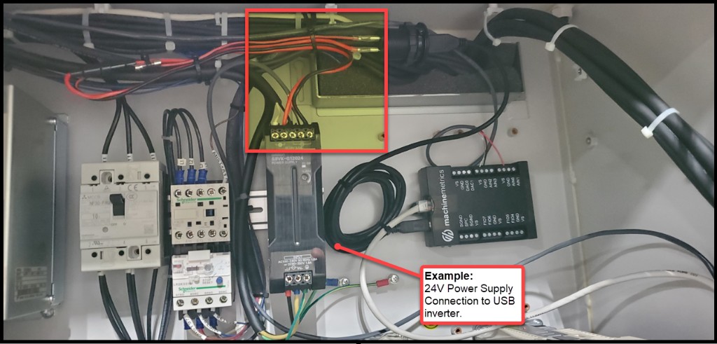
Example: 24VDC power supply connection to the USB inverter. Layout will vary by machine model.
Step 2 — Locate the External Output Terminal Block (XTO)
Brother CNCs are equipped with a block of terminals that can be programmed to energize in conjunction with specific machine states or M-codes. This terminal block is called the XTO (External Terminal Output) and is located on a circuit board inside the electrical cabinet.
Finding the XTO:
- Look for circuit boards labeled XTO — do not confuse with XTI (External Terminal Input)
- There are typically two XTO terminal blocks on the same board:
- Orange block (PNP) — outputs 24VDC when the assigned signal is active ✅ Preferred
- Gray block (NPN) — opens 0V when active (requires a relay to pass signal to the I/O module)
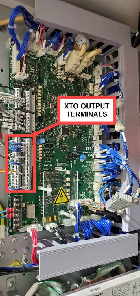
XTO terminal block location inside the Brother electrical cabinet.
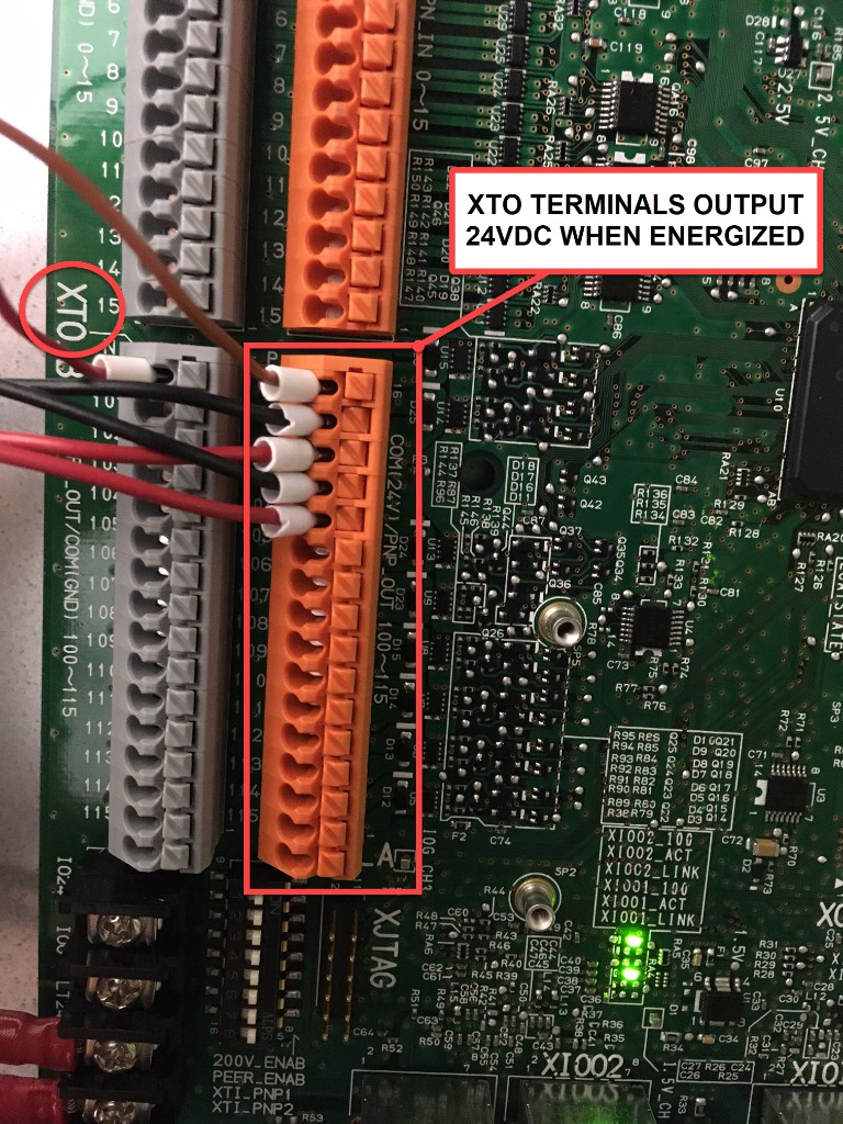
The orange (PNP) XTO terminals output 24VDC when active. Both the orange and gray blocks are XTO terminals numbered consistently.
Identify 2–3 unoccupied terminals on the XTO block that you will program in the next step.
Step 3 — Program the XTO Outputs
With unoccupied terminals identified, navigate to the External Output Signal programming screen on the controller.
Navigation path:
- Press the DATA BANK hard key on the controller
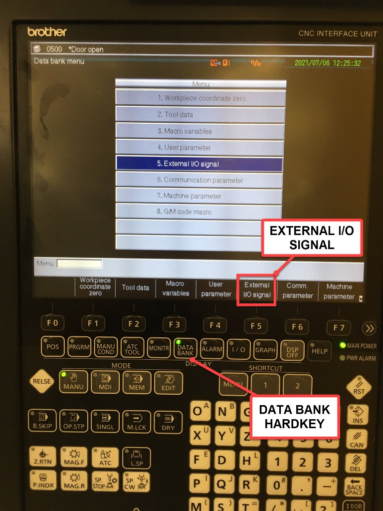
-
If the menu shows "External I/O Signal" as a softkey, press it directly.
If the menu instead shows "User Parameter", press that softkey first:
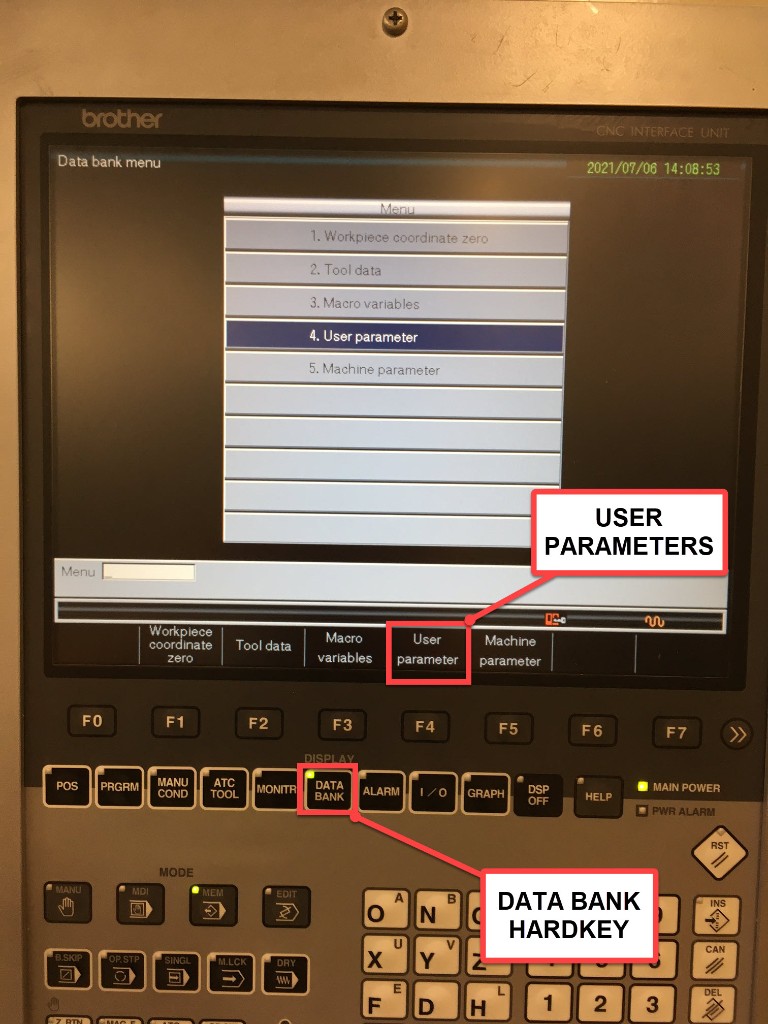
- From the User Parameters screen, if "External I/O Signal" is not visible, press Next Menu:
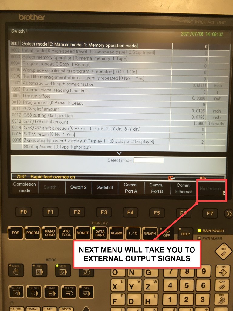
- You will arrive at the External Output Signal screen. The lower half of the screen lists signal abbreviations (machine states and M-codes). The upper half shows the terminal assignments.
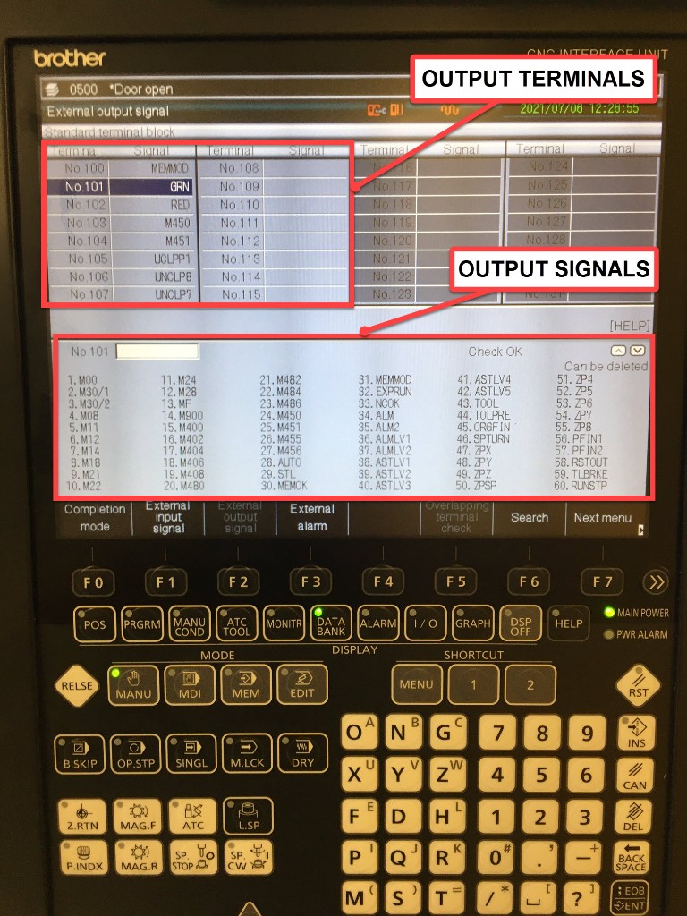
Recommended signal assignments:
| Terminal | Signal | Purpose |
|---|---|---|
| XTO terminal (e.g., No.333) | GRN | Green stack light — machine active state |
| XTO terminal (e.g., No.334) | M450 | M-code pulse — part count trigger |
| XTO terminal (e.g., No.335) | ALM | Alarm state |
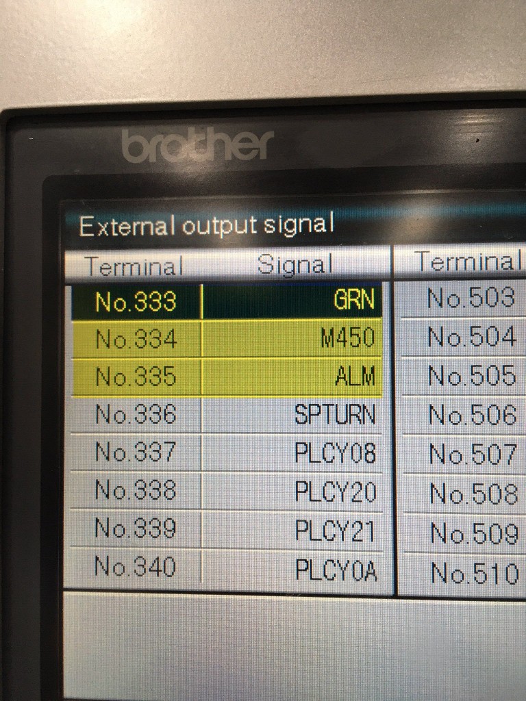
Signal notes:
GRN— Energizes whenever the green stack light signal is active (regardless of whether a physical light is installed). Reliable indicator of machine activity.M450— Sends a momentary 24VDC pulse when theM450;command executes in a part program. Since M450 has no other machine function, it is ideal for part count. AddM450;to your part program at the point of part completion.ALM— Energizes when the machine is in an alarm state.
After assigning signals to XTO terminals, be sure to save before exiting. The save method varies by controller — look for a "Write" or "Save" softkey, or press INPUT to confirm each entry.
Step 4 — Wire XTO Terminals to the I/O Module
Connect the programmed XTO terminals to the analog inputs of the Sealevel eI/O-170 module:
| Sealevel Input | XTO Signal | Purpose |
|---|---|---|
| AN1 (address 0) | GRN (green stack light) | Utilization / execution state |
| AN2 (address 1) | ALM (alarm) | Alarm state |
| AN3 (address 2) | M450 (part count pulse) | Part count |
The XTO PNP outputs supply 24VDC when active. The Sealevel eI/O-170 analog inputs only accept 0–10VDC, so the 24VDC XTO signals must be passed through 24VDC relays before connecting to the Sealevel AN terminals. If you are using a WISE module instead, it can accept 24VDC inputs directly and no relay is required.
Step 5 — Adapter Script
With GRN wired to AN1, ALM to AN2, and M450 to AN3, use the following adapter script:
version: 2

registers:
  green-light-raw:
    address: 0 # AN1 — GRN (green stack light)
    func: 4
    type: int16

  red-light-raw:
    address: 1 # AN2 — ALM (alarm)
    func: 4
    type: int16

  part-count-raw:
    address: 2 # AN3 — M450 part count pulse
    func: 4
    type: int16

variables:
  green-voltage:
    - source: green-light-raw / 409.6
    - resample: 0.5
    - min-delta: 0.1

  execution:
    - source: green-light-raw / 409.6
    - threshold: 3
    - off-delay: 10
    - state:
        - ACTIVE: this
        - READY: true

  alarm:
    - source: red-light-raw / 409.6
    - threshold: 3

  part-count:
    - source: part-count-raw / 409.6
    - threshold: 3
    - rising-edge
    - count

data-items:
  - execution
  - part-count
  - green-voltage
  - alarm

conditions:
  system:
    message: Machine is in fault state
    value:
      FAULT: alarm
Script notes:
threshold: 3treats anything above ~3V as a logic HIGH (appropriate for 24VDC signals read through the 0–10V analog input range)off-delay: 10holds the ACTIVE state for 10 seconds after the green light drops — prevents state flickering during brief tool changes- The
alarmvariable reads the ALM signal from AN2 and feeds theconditionsblock — both the data item and the fault condition will reflect alarm state - Adjust
thresholdif your signals read differently based on your wiring configuration
Machine-Specific Integrations
Haas CNC Machines (Pre 2001)
Recommended Configuration:
- Hardware: Sealevel eI/O-170E
- AN1: Spindle CT (analog 0-10V)
- Opto 1: Part count relay or coolant contactor
Adapter Script:
version: 2
unit-id: 1

registers:
  spindle-raw:
    address: 0 # AN1
    func: 4
    type: int16

coils:
  part-signal:
    address: 0
    func: 2 # Read Discrete Inputs

variables:
  # Spindle monitoring (intermediate conversion)
  spindle-voltage-int:
    - source: spindle-raw / 409.6

  # Cleaned version for data output
  spindle-voltage:
    - source: spindle-voltage-int
    - resample: 0.5
    - min-delta: 0.1

  execution:
    - source: spindle-voltage-int > 1.15
    - off-delay: 10
    - state:
        - ACTIVE: this
        - READY: true

  part-count:
    - source: part-signal
    - rising-edge
    - count

data-items:
  - execution
  - part-count
  - spindle-voltage
Citizen/Miyano Lathes
Recommended Configuration:
- Hardware: Sealevel eI/O-170E
- AN1: Main spindle CT
- AN2: Sub spindle CT (if applicable)
- Opto 1: Work count relay
Adapter Script:
version: 2
unit-id: 1

registers:
  main-spindle-raw:
    address: 0 # AN1
    func: 4
    type: int16

  sub-spindle-raw:
    address: 1 # AN2
    func: 4
    type: int16

coils:
  work-count:
    address: 0
    func: 2 # Read Discrete Inputs

variables:
  # Convert CTs to voltage (intermediate)
  main-voltage-int:
    - source: main-spindle-raw / 409.6

  sub-voltage-int:
    - source: sub-spindle-raw / 409.6

  # Cleaned versions for data output
  main-voltage:
    - source: main-voltage-int
    - resample: 0.5
    - min-delta: 0.1

  sub-voltage:
    - source: sub-voltage-int
    - resample: 0.5
    - min-delta: 0.1

  # Active if either spindle running
  execution:
    - source: main-voltage-int > 1.0 or sub-voltage-int > 1.0
    - off-delay: 10
    - state:
        - ACTIVE: this
        - READY: true

  part-count:
    - source: work-count
    - rising-edge
    - count

data-items:
  - execution
  - part-count
  - main-voltage
  - sub-voltage
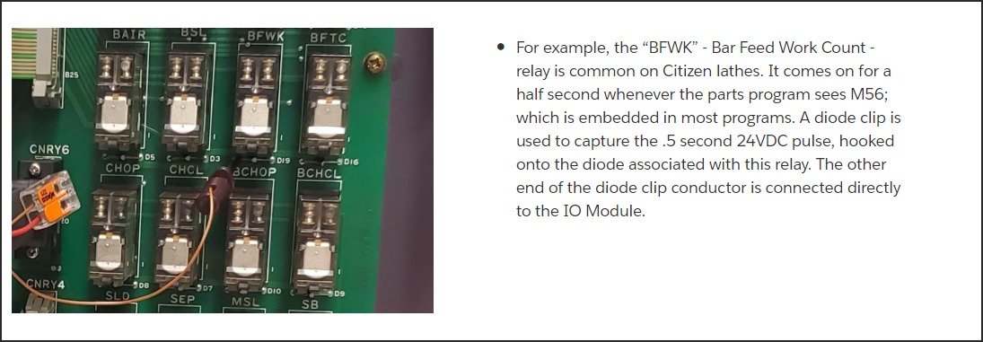
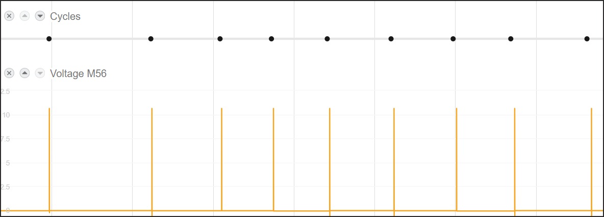
Part Count — BFWK Bar Feed Work Count Relay (Citizen/Cincom)
On Citizen Cincom lathes, the BFWK relay (Bar Feed Work Count) fires for approximately 0.5 seconds whenever the parts program executes M56. A diode clip captures the 24VDC pulse from the relay's back-EMF diode and connects directly to the I/O module.
Mori Seiki / DMG MORI Machines
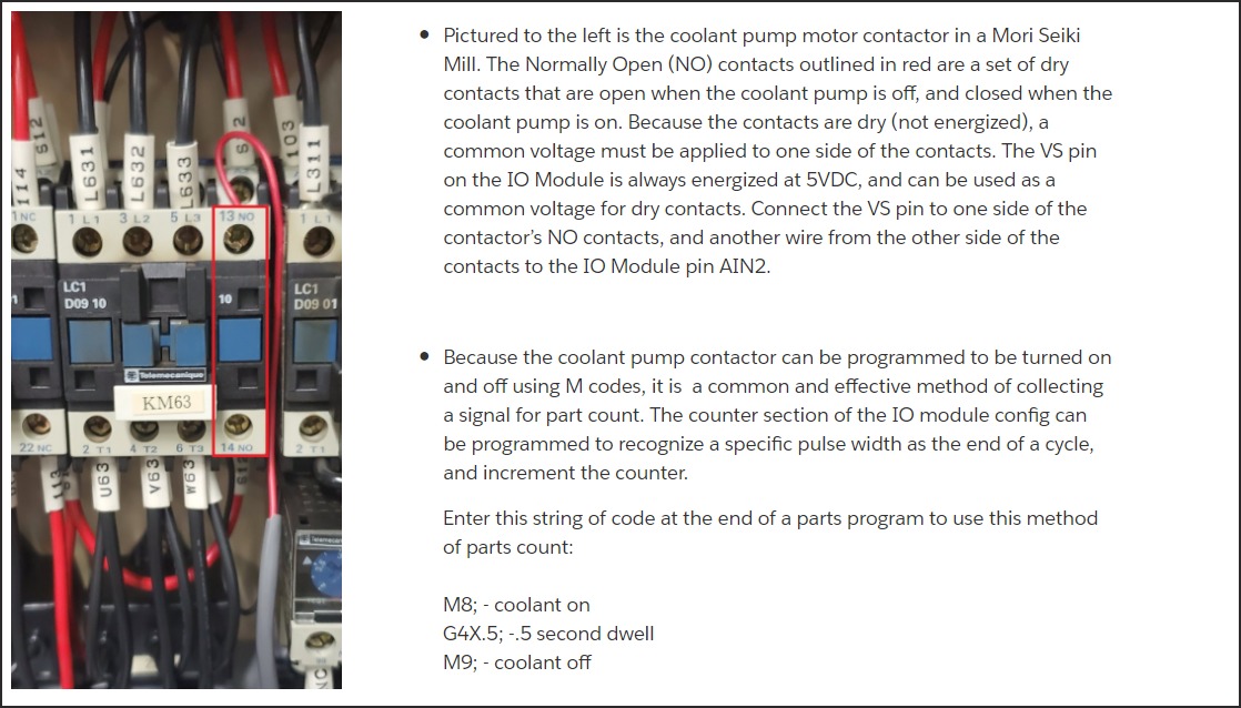
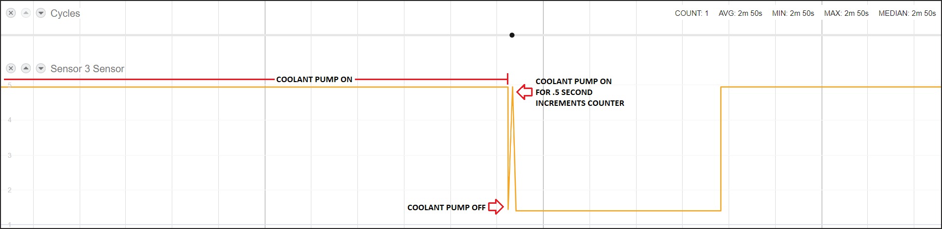
Part Count — Coolant Pump Contactor (Dry Contact Method)
On Mori Seiki and DMG MORI machines, the coolant pump contactor (often labeled KM63) provides a reliable set of dry Normally Open (NO) contacts for part counting. Because the contacts are dry (no voltage present), connect the VS pin (5VDC) of the I/O module to one side, and the other side to the AIN input.
Add this G-code string at the end of each parts program to pulse the coolant pump for part counting:
M8;   (coolant on)
G4X.5; (.5 second dwell)
M9;   (coolant off)
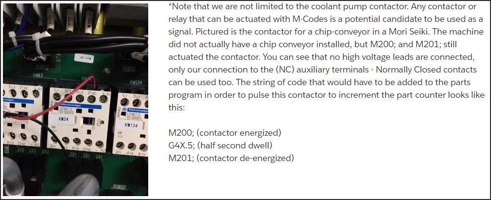
Part Count — Chip Conveyor or Spare M-Code Contactor
Any M-code-actuated contactor is a candidate. The chip conveyor contactor (shown below on a Mori Seiki) may not have a chip conveyor installed, but M200/M201 still actuate the contactor — giving you a free normally-closed (NC) contact that can be used as a part count signal.
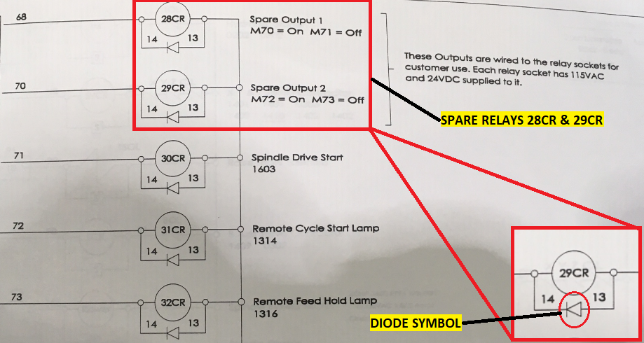
Part Count — Spare M-Code Relays (HMCs)
Horizontal machining centers (HMCs) often have spare output relays (e.g., 28CR / 29CR actuated by M70/M71) pre-wired to relay sockets with 24VDC already supplied. The ladder diagram shows the diode symbol indicating the coil polarity — hook a diode clip to the appropriate relay's diode legs.
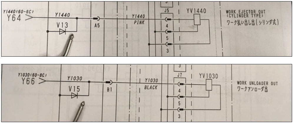
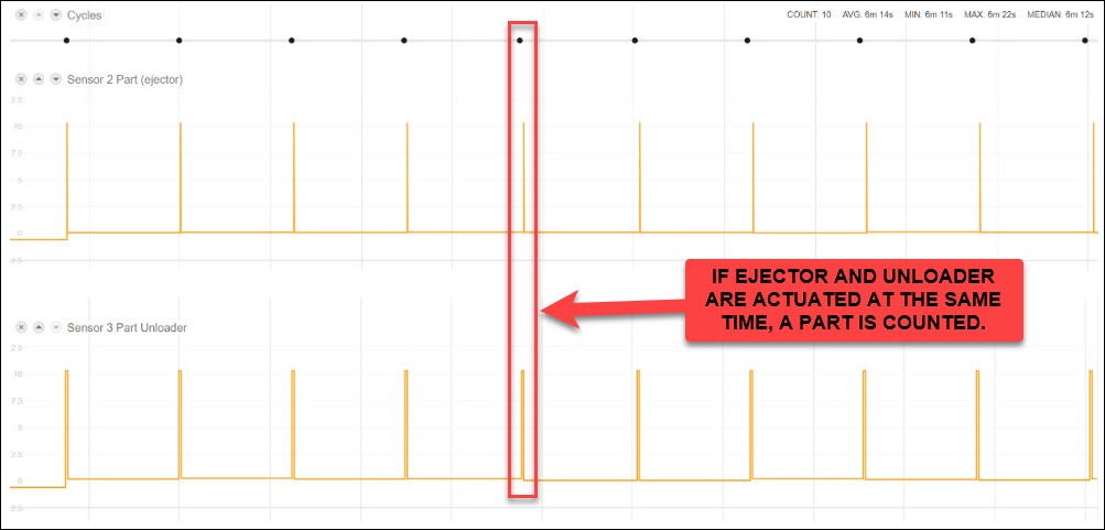
Work Ejector / Unloader Part Count (Mazak, Okuma, and others)
Some machining centers count parts by monitoring two signals simultaneously: the Work Ejector output (Y1440) and the Work Unloader output (Y1030). A part is counted only when both signals are active at the same time.
Step 1: Find Ejector and Unloader signals in the ladder diagram
Step 2: Identify and tap the diodes on the PCB
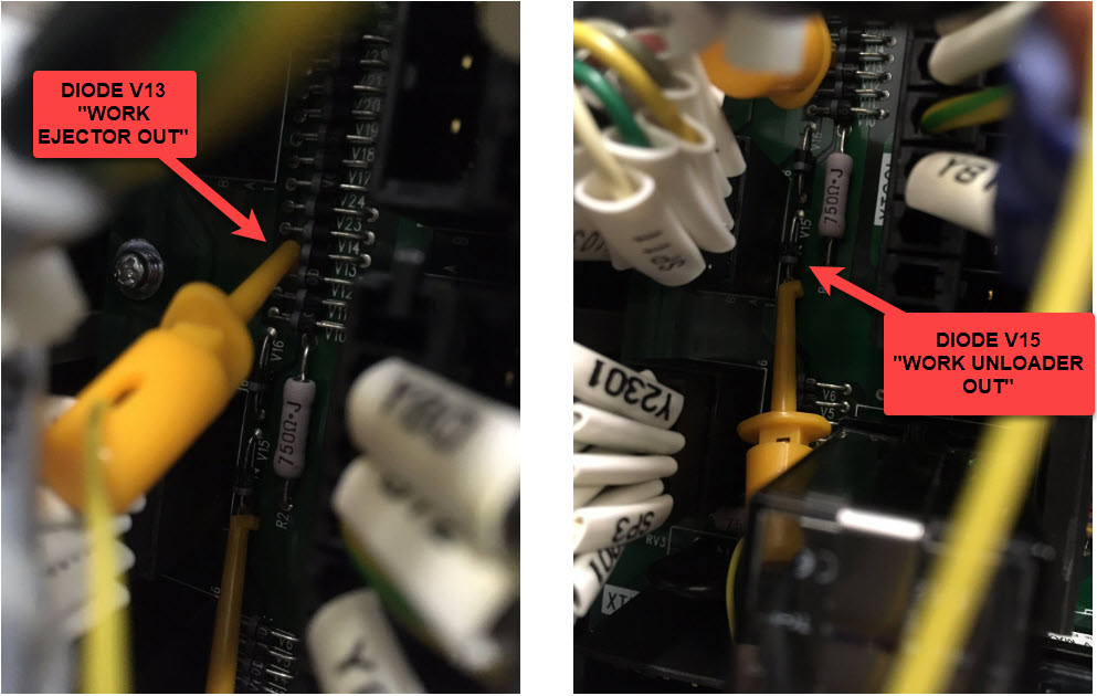
Step 3: Verify in MachineMetrics
Wire the ejector to AIN1 (Sensor 2) and the unloader to AIN2 (Sensor 3). In the adapter script, count a part only when both sensors are simultaneously active.
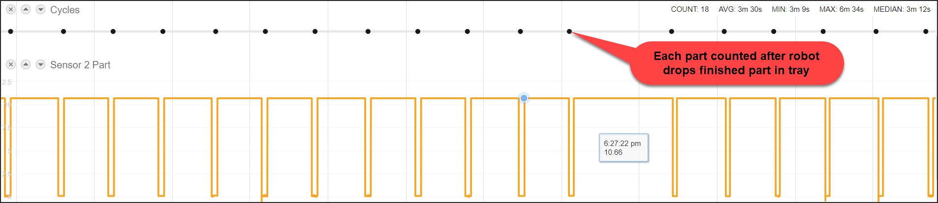
For robot-unloaded cells, the robot's part-drop signal (e.g., a relay when the finished part is placed in the tray) can be used as a single-sensor part count:
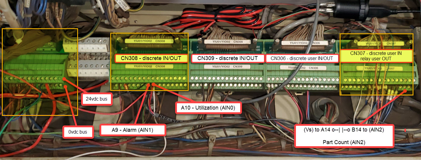
Yaskawa Robot Integration
Yaskawa DX200 and similar robot controllers expose discrete I/O through CN308 / CN309 / CN306 / CN307 terminal blocks. The I/O module connects directly to the appropriate terminal.
Press Brakes
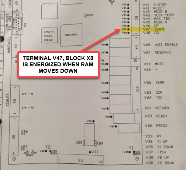
Press brakes are monitored by detecting the Ram Down signal — the output that fires each time the ram completes a stroke (one stroke = one part bend).
Step 1: Locate the Ram Down terminal in the ladder diagram
The Ram Down signal is typically labeled DOWN or V47 in the press's schematic:
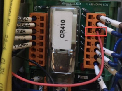
Step 2: Find the physical relay or terminal block
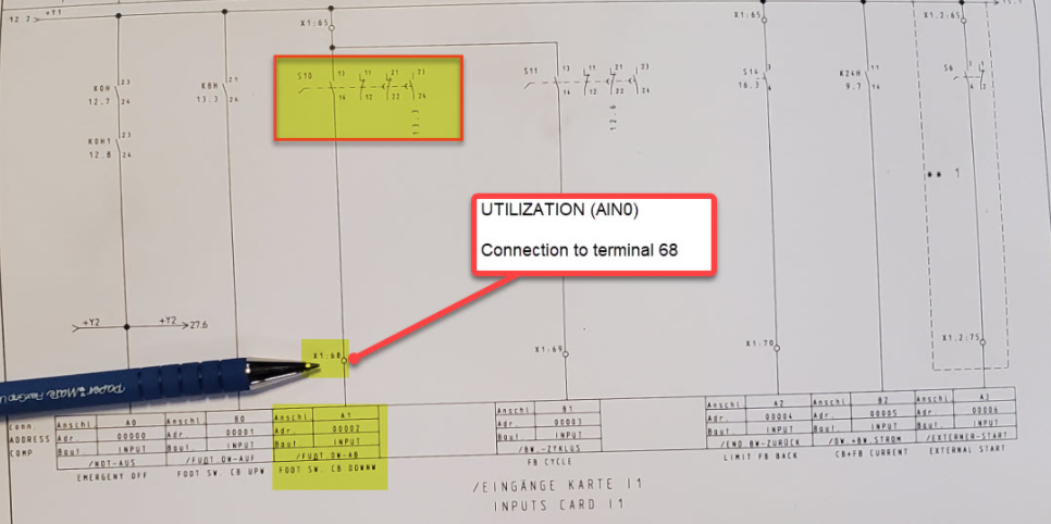
Step 3: Identify the Utilization signal (if using a separate input)
For machines where a separate Utilization (AIN0) signal is desired (e.g., foot switch or "Press Active" state), identify the corresponding input card terminal:
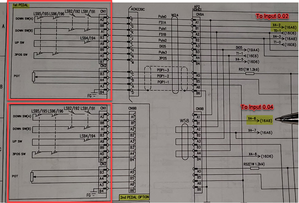
For machines with foot pedals, the Down Switch signals route through CNs and connect to the I/O module inputs:
Step 4: Verify Ram Down signal in MachineMetrics
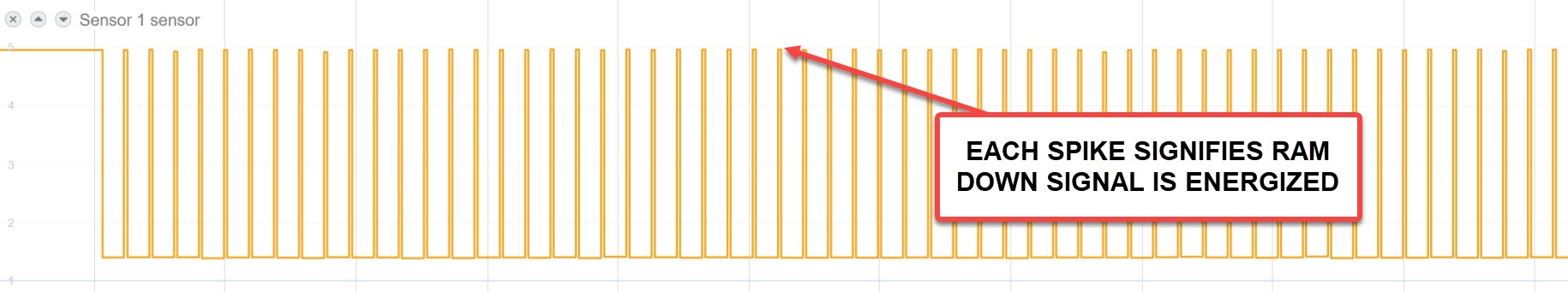
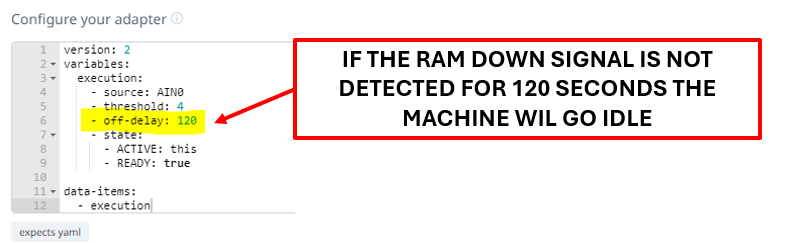
Step 5: Configure the adapter script
Because press brakes cycle very rapidly, set an off-delay (e.g., 120 seconds) so the machine doesn't flip to idle between strokes:
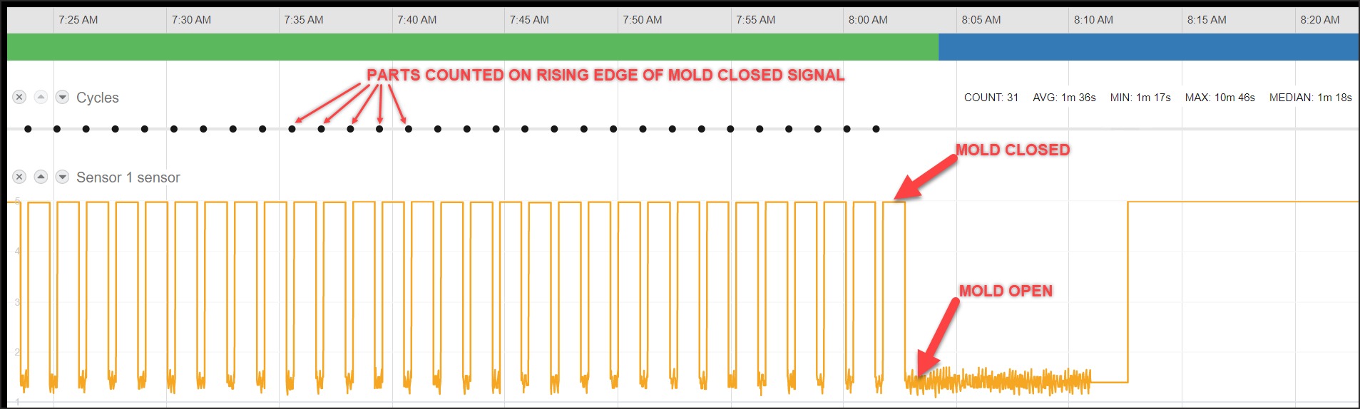
Injection Molding Machines
Injection molding machines are monitored through the mold-closed output — a signal that fires each time the mold closes (one close = one cycle, one part). Parts are counted on the rising edge of the mold-closed signal.
Troubleshooting
Cannot Connect to Module
Diagnostic Steps:
- Check Power
- Sealevel: Power LED green?
- WISE: Power LED on?
- Measure voltage at terminals: 24VDC ±10%
- Check Network
- Cable fully seated in RJ45?
- Link lights blinking?
- Try different cable or switch port
- Check IP Address
- Sealevel default: 192.168.42.253
- WISE default: 192.168.1.1 or DHCP
- Is computer on same subnet?
- Ping Module
- Open command prompt
ping 192.168.42.253(or module IP)- Should receive replies
Signal Not Detected
Diagnostic Steps:
- Measure Voltage
- Use multimeter
- Measure between input terminal and common
- Should read signal voltage when active
- Should read near 0V when inactive
- Check Wiring
- Terminals tight?
- Correct polarity?
- Any broken wires?
- Verify Modbus Address
- Sealevel: AI0=register 0, Opto 1=coil 0
- WISE: DI0=coil 0, DI1=coil 1, etc.
- Test with Configuration Tool
- Sealevel: Use MaxSSD utility
- WISE: Use web interface diagnostics
- Confirm signal reaches module
Current Transducer (CT) State Detection Issues
Current transducers measure electrical current to determine machine state (Active/Idle). Use this systematic approach to diagnose and resolve CT-related issues.
Common Symptoms:
- Machine shows Idle while physically running
- Machine shows Active while physically idle
- Erratic switching between Active and Idle states
- Machine state never changes
⚠️ CRITICAL PRINCIPLE: When a machine is completely idle (spindle off, no motors running), the CT voltage should be very low (typically 0.5V - 1.5V). If you see high voltage during idle, the CT is in the wrong location or measuring the wrong circuit.
Understanding CT Switch Positions
Most analog CTs (0-10V output) have three switch positions that determine the current measurement range:
| Switch Position | Current Range | When to Use |
|---|---|---|
| 1 (Low) | 0-50A | Small motors, low-power equipment |
| 2 (Medium) | 0-100A | Most spindle motors, typical CNC equipment |
| 3 (High) | 0-200A | Large motors, high-power machines |
How to Choose: Check the motor nameplate for rated current, then select the switch position that covers that range. Too low = CT maxes out; too high = poor signal separation.
Diagnostic Steps:
-
Review Current Configuration
- Navigate to Machines → [Machine] → Settings → Data Collection
- Document current threshold value and off-delay setting
-
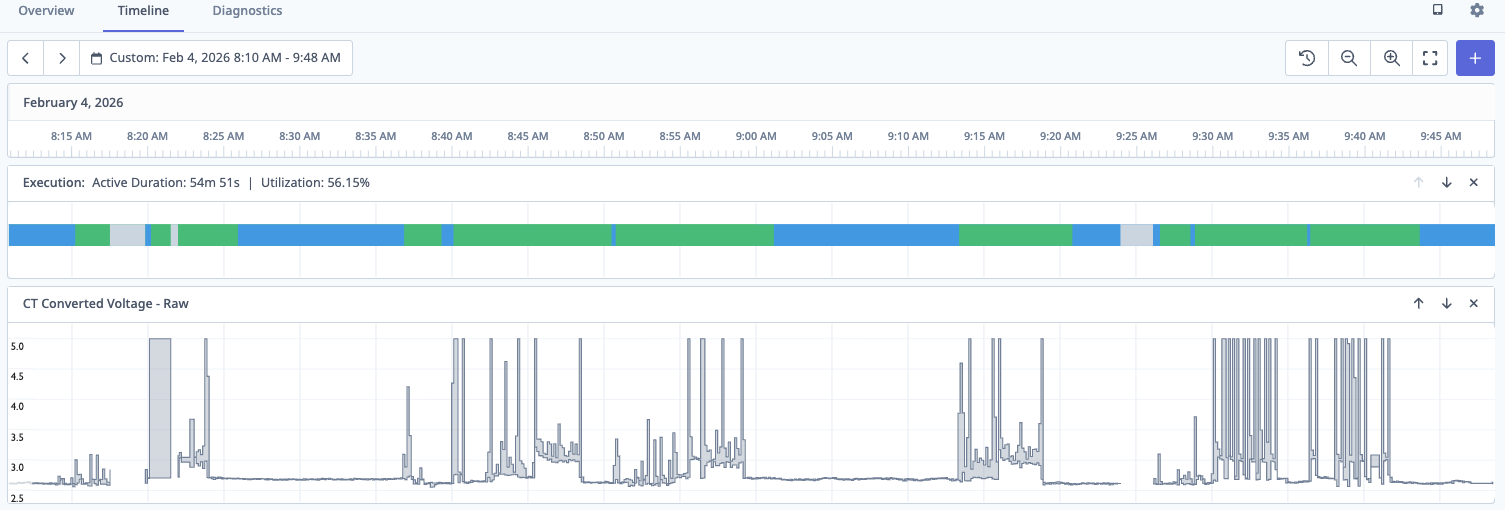
Observe CT Behavior in Timeline
- Go to Machine → Timeline view and enable Live Mode
- Add "CT Converted Voltage - Raw" data item to timeline
- Watch the signal for several minutes while machine cycles
-
Verify Physical Installation
| Checkpoint | ✅ Correct | ❌ Incorrect |
|---|---|---|
| Clamp closure | Fully closed, no gap | Gap visible between halves |
| Cable type | Single conductor only | Multiple wires or cable bundle |
| Location | Spindle motor or main power | General building power |
| Interference | 18"+ from VFDs/transformers | Adjacent to high-voltage equipment |
- Perform Live Testing (Most Critical Step)
Stand at the machine and observe CT voltage during these states:
Test A: Machine Completely Idle
- Spindle OFF, no motors running
- Record idle voltage range (should be < 2.0V)
- If higher: CT is on wrong circuit or switch position too high
Test B: Spindle Running (Not Cutting)
- Start machine, activate spindle at normal speed
- Record active voltage range
Test C: Production (Cutting)
- Load part and begin cutting operation
- Record cutting voltage range
- Calculate Optimal Threshold
Optimal Threshold = (Max Idle Voltage + Min Active Voltage) / 2
Example:
- Idle range: 0.8V to 1.5V (Max = 1.5V)
- Active range: 3.2V to 5.0V (Min = 3.2V)
- Calculation: (1.5 + 3.2) / 2 = 2.35V
- Set threshold to 2.3V or 2.5V
⚠️ Important: You need at least 0.5V separation between max idle and min active.
- Update Adapter Script Configuration
Navigate to Machines → [Machine] → Settings → Data Collection and update your adapter script:
variables:
  # Intermediate variable for logic (not output)
  ct-voltage-int:
    - source: spindle-raw / 409.6 # SeaLevel conversion

  # Cleaned variable for data output
  ct-voltage:
    - source: ct-voltage-int
    - resample: 0.5 # Sample every 0.5 seconds
    - min-delta: 0.1 # Only send if changed by 0.1V

  # Execution state based on threshold
  execution:
    - source: ct-voltage-int > 2.5 # Your calculated threshold
    - off-delay: 90 # Optional delay in seconds
    - state:
        - ACTIVE: this
        - READY: true

data-items:
  - execution
  - ct-voltage # Output cleaned variable only
⚠️ CRITICAL Variable Naming:
- Always use TWO variables for CT voltage
- Intermediate variable (
ct-voltage-int): Used for threshold logic, never include in data-items - Cleaned variable (
ct-voltage): Usesresampleandmin-deltato reduce noise, safe for data-items - This prevents database overload from noisy analog signals
Common CT Issues & Quick Solutions:
No voltage signal (flat line at 0V)
- Check physical connections at IO module
- Verify Modbus register address in script
- Test with multimeter or swap CT
Constant high voltage (even when machine is off)
- Turn machine off at breaker - CT should drop to ~0V
- If signal persists, CT is on wrong circuit
- Relocate to machine-specific circuit (spindle motor)
- Ensure only single conductor in CT clamp
- Check CT switch position - try higher range setting
Extreme noise / erratic signal
- Move CT 18"+ away from VFDs and transformers
- Reroute CT cable away from high-voltage runs
- Verify cable shielding is intact
Typical Voltage Ranges (Quick Reference):
| Machine State | Typical Voltage | Diagnosis |
|---|---|---|
| Completely Off (breaker off) | 0V - 0.2V | No current flowing |
| Idle / Standby | 0.5V - 1.5V | ✅ Normal baseline |
| ⚠️ High Idle (PROBLEM) | 2.5V - 4.0V | ❌ Wrong circuit or multiple conductors |
| Spindle Running (no load) | 2.5V - 4.0V | Clear increase from idle |
| Cutting / Under Load | 3.5V - 5.0V | Peak activity |
When to Contact Support:
- No voltage signal despite verified connections
- CT signal doesn't correlate with machine behavior
- Overlapping idle/active voltage ranges after relocating CT
- Adapter script changes don't take effect
Include: Machine name, Timeline screenshots showing CT voltage, documented voltage ranges, photos of CT installation, and current adapter script.
False Part Counts
Solutions:
-
Add Auto Mode Logic
part-count:
  - source: part-signal and auto-mode
  - rising-edge
- count -
Add Pulse Duration Verification (for coolant method)
filtered-signal:
  - source: raw-signal
  - min-delta: 0.4
- max-delta: 0.7 -
Use Correct Edge Detection
- Try
rising-edgevsfalling-edge - Depends on signal behavior
- Try
Best Practices
Planning:
- Study machine operation before selecting signals
- Review electrical schematics
- Test signals under various conditions
- Document everything
Current Transducers:
- Use analog 0-10V CTs for Sealevel eI/O-170 analog inputs
- Use dry contact CTs for Sealevel eI/O-170 digital inputs (Opto 1/2)
- Clamp around ONE phase only
- Secure CT to prevent vibration
- Set low threshold (1.0-1.5V) for low-speed detection
Wiring:
- Use 18-22 AWG stranded wire
- Label all wires clearly
- Keep wiring neat and organized
- For Sealevel digital inputs: DO NOT apply external voltage (internally powered)
Electrical Safety:
- Never apply >50VDC to any input
- Use relays for AC voltages
- Verify voltage with multimeter
- Follow lockout/tagout procedures
- Work with qualified electricians
Configuration:
- Start with simple adapter scripts
- Test incrementally
- Use descriptive variable names
- CRITICAL: Never output raw analog values in
data-items- Create intermediate variable for logic (e.g.,
ct-voltage-int) - Create cleaned variable with
resampleandmin-deltafor output - Only output cleaned variables to reduce noise and database load
- Create intermediate variable for logic (e.g.,
- Reference: https://developers.machinemetrics.com/docs/adapter-scripts/intro
- Keep backup of working configurations
Part Counting:
- Prefer dedicated part count relay
- Use pallet changer signal when available
- Use barfeeder pulse when applicable
- Coolant pulse method is last resort only
Additional Resources
MachineMetrics Developer Documentation:
- Adapter Scripts Introduction: https://developers.machinemetrics.com/docs/adapter-scripts/intro
- Available Operations: https://developers.machinemetrics.com/docs/adapter-scripts/operations
Sealevel Resources:
- SeaMAX Software Download: https://www.sealevel.com/software-seamax-windows
- eI/O-170 Product Page: https://www.sealevel.com
- Technical Support: (864) 843-4343 or support@sealevel.com
Advantech Resources:
- WISE-4050 Product Page: https://www.advantech.com
- WISE-4050 User Manual (see provided PDF)
- Technical Support: www.advantech.com/support
Purchasing:
- Sealevel eI/O-170: Order from shop.machinemetrics.com
- WISE-4050: Customer-sourced from Advantech or distributors
- Current Transducers: NK Technologies, CR Magnetics, Veris
Getting Help
Before Contacting Support
Gather this information:
- Hardware Details
- Module model (eI/O-170E or WISE-4050)
- Module IP address
- Can you ping the module?
- Machine Details
- Make, model, year
- What signals are you monitoring?
- Signal Information
- What is each input connected to?
- Voltage measurements with multimeter
- Wet or dry contact?
- For CTs: Analog or dry contact output?
- Adapter Script
- Current script (copy/paste)
- What behavior are you seeing vs. expecting?
Contact Options
MachineMetrics Support:
- Email: support@machinemetrics.com
- Include all information above
- Attach photos of wiring
- Include complete adapter script
For Sealevel Hardware:
- Sealevel Support: (864) 843-4343
- Email: support@sealevel.com
- Hardware-specific questions
For WISE Hardware:
- Advantech Support: www.advantech.com/support
- Hardware configuration questions
Ready to connect your machine with I/O?
- Choose hardware: Sealevel eI/O-170 (wired/PoE) or WISE-4050 (wireless)
- Identify signals: CT for execution, appropriate part count method
- Install module and wire signals
- Configure network (static IP)
- Create Modbus TCP adapter script
- Test and refine
Questions? Contact support@machinemetrics.com